
Hose Clamp

a technology of hose clamping and axial clamping, which is applied in the direction of hose connection, pipe/joint/fitting, mechanical apparatus, etc., can solve the problems of leakage in connection with high pressure lines, inadequate material resilience of the clamp band, etc., and achieve the effect of increasing the flexibility of the clamping in an axial direction and the degree of clamping flexibility

Inactive Publication Date: 2019-07-18
NORMA GERMANY GMBH
View PDF0 Cites 0 Cited by
  • Summary
  • Abstract
  • Description
  • Claims
  • Application Information

AI Technical Summary

Benefits of technology

The patent describes a modification to an existing structure by adding two new structures that run in an axial direction and meet at a point. These structures also run in a radial direction. This modification allows for better contact between the surface of a member and the clamp band, via which the clamp's strength is transmitted. The new structures provide the clamp band with a resilience to compensate for changes in the size of the hose or pipe due to temperature variations. Additionally, there is a notch in the clamp band that increases its flexibility in the axial direction.

Problems solved by technology

If hose clamps are fitted to rigid pipe ends or the like, it may be the case, for example, in the event of significant temperature changes, that the material resilience of the clamp band is not adequate in order, for example, in the event of a temperature-related expansion of the pipe end or the like, to prevent a clamping excess rise in the clamp band.
In a disadvantageous manner, in a state distributed over the periphery, the abutment of the clamp band, for example, against a non-resilient particularly round member, is not ensured over the entire periphery thereof, but is instead interrupted in the region of the undulating structure.
Therefore, there may be occurrences of leakage in connection with high pressure lines.

Method used


Image

  • Hose Clamp
  • Hose Clamp
  • Hose Clamp

Examples


Embodiment Construction

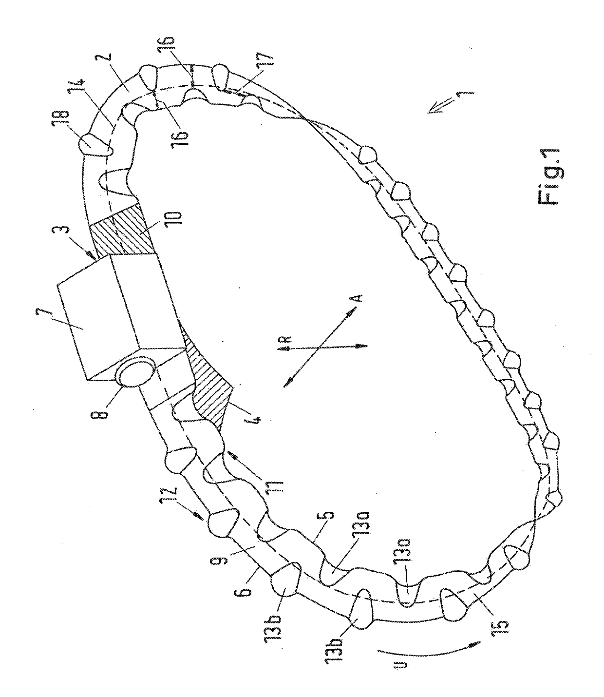
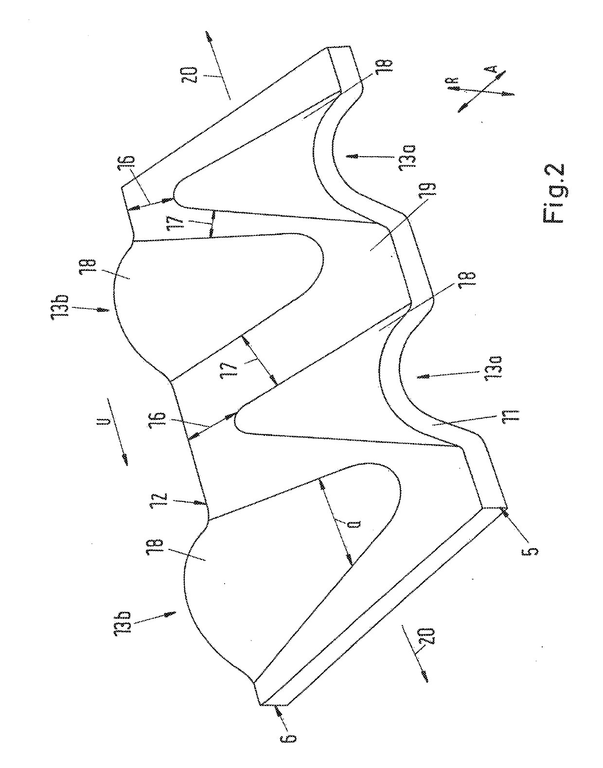
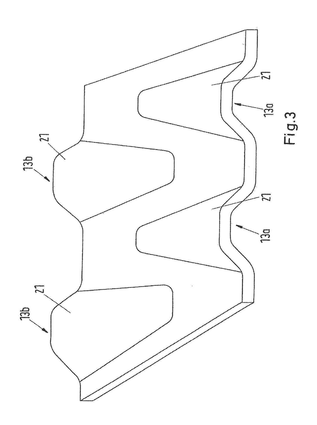
[0029]FIG. 1 shows a clamp 1 having a clamp band 2 which has a first end 3, a second end 4, a first edge 5 and a second edge 6. Furthermore, the clamp has a clamping device 7 having a clamping screw 8 and the clamp band 2 has a structure portion 9 and an additional portion having a thread embossing 10. The clamping device 7 is arranged on the first end 3 of the clamp band 2 whilst the thread embossing 10 is arranged on the second end 4 of the clamp band 2. There is arranged between the first end 3 and the portion with the thread embossing 10 the structure portion 9 inside which on the first edge 5 a first structure 11 and on the second edge 6 a second structure 12 are arranged. The structures 11, 12 are composed in each case of formations 13a, 13b which are arranged alternately in a peripheral direction U and which extend from the respective edge 5, 6 over the center axis 14. Therefore, the formations 13 extend in an axial direction A. Furthermore, the formations 13 extend in a radi...


PUM


Abstract

The disclosure relates to a clamp (1), comprising a clamp band (2) extending in a peripheral direction (U) and a tensioning device (7) for tensioning the clamp band (2). According to an embodiment, in order to form the clamp (1) with yielding properties during tensioning and from a minimal number of structural components, the clamp band (2) has structures (11, 12) that extend at the edges (5, 6) of the clamp band.

Description

INTRODUCTION[0001]The present disclosure relates to a hose clamp having a clamp band which extends in a peripheral direction and having a clamping device for clamping the clamp band.[0002]An example of a generic hose clamp is set out in U.S. Pat. No. 4,308,648 A1. The hose clamp has a clamping device via which a clamp band can be clamped, for example, around a hose end or the like. The clamping device has to this end a clamping screw which is rotatably received in a housing of the clamping device. In this instance, as a result of a thread of the clamping screw, the clamp band, which on the outer side thereof has a corresponding engagement geometry for the thread, can be pulled into the housing of the clamping device. During clamping, the diameter of the hose clamp decreases accordingly and radial clamping forces are produced.[0003]If hose clamps are fitted to rigid pipe ends or the like, it may be the case, for example, in the event of significant temperature changes, that the mater...

Claims


Application Information

Patent Timeline
Patent Type & Authority Applications(United States)
IPC IPC(8): F16L33/035F16L33/08
CPCF16L33/035F16L33/08F16L33/04
Inventor LEUSNER, OLIVERGEPPERT, HELMUTVON BREITENBACH, GERRITBREIDEBAND, LINDASOMMER, MICHAELLENZ, MICHAEL
Owner NORMA GERMANY GMBH
Learn More