Stack mold

a mold and stout technology, applied in the field of stout molds, can solve the problems of time-consuming operation and rack-and-pinion structure, and achieve the effects of rapid adjustment, easy and rapid demounting and mounting, and flexibility and ease of operation

Inactive Publication Date: 2001-06-26
KODRIC JOSEPH
View PDF4 Cites 21 Cited by
  • Summary
  • Abstract
  • Description
  • Claims
  • Application Information

AI Technical Summary

Benefits of technology

The present invention represents an improvement on the prior art, permitting a degree of flexibility and ease of operation which has not previously been achieved. The present invention provides a universal rack-and-pinion structure for use with stack molds, which is readily and rapidly demounted and mounted and permits rapid adjustment for proper proportioning of movement of the moveable mold parts in a stack mold in a molding machine.

Problems solved by technology

When access to the mold parts is required for removal from the molding machine and replacement by another stack mold, the rack-and-pinion structure often needs to be first removed and then subsequently reassembled, a time consuming operation.

Method used


Image

  • Stack mold
  • Stack mold
  • Stack mold

Examples


Embodiment Construction

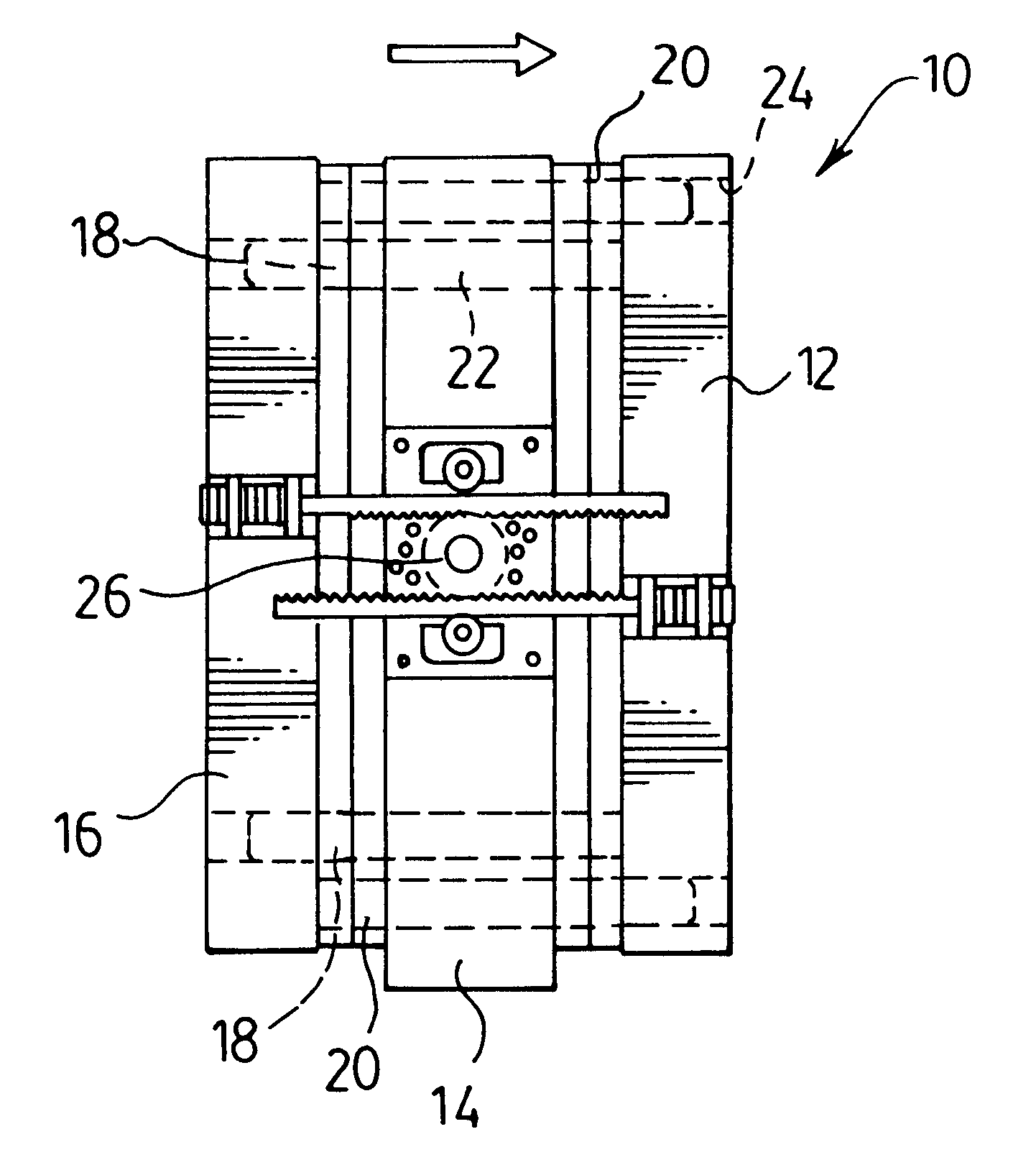
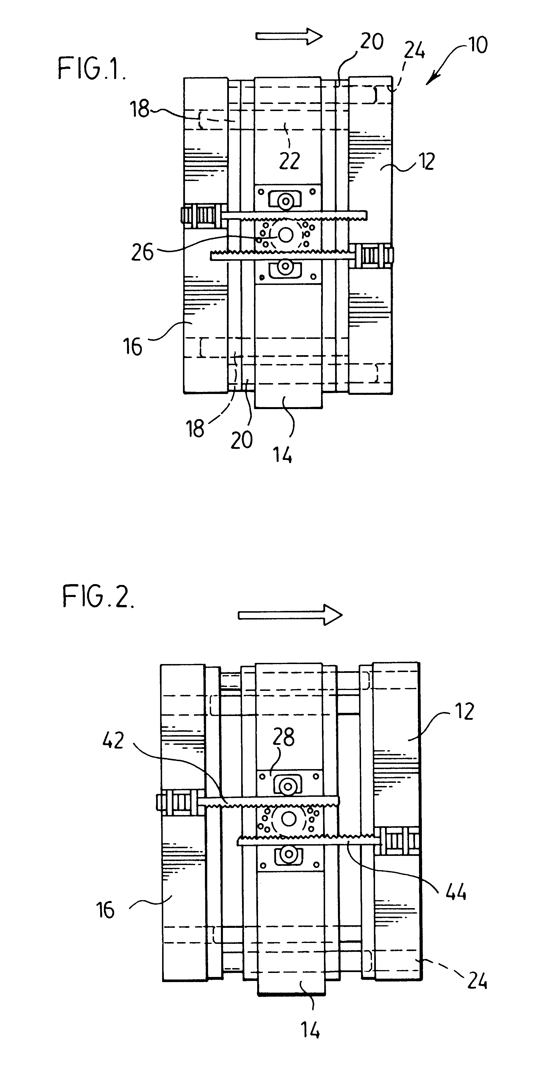
Referring first to FIGS. 1 and 2, a stack mold 10 comprises an end stationary mold part 12 and a pair of moveable mold parts 14, 16 moveable into and out of mold-cavity forming relationships between the inner moveable mold part 14 and the stationary mold part 12 and between the outer moveable mold part 16 and the inner moveable mold part 14.

The moveable mold parts 14, 16 are arranged in sliding relationship with the stationary mold part 12 by guide pins 18, 20. The guide pins 18, 20 protrude respectively from the stationary mold part 12 and outer moveable mold part 16, through openings 22 in the central moveable mold part 14 and into recesses 24 formed in the stationary mold part 12 and the moveable mold part 14 when in the closed position (FIG. 1).

In order for the stack mold to function correctly within a molding machine, it is necessary for the mold cavities to be formed between the stationary mold part 12 and the inner moveable mold part 14 and the mold cavity to be formed betwee...


PUM

PropertyMeasurementUnit
distanceaaaaaaaaaa
sizeaaaaaaaaaa
timeaaaaaaaaaa

Abstract

A universal mountable and demountable rack-and-pinion structure for a stack mold includes mounting plates affixed to the mold parts and rack-and-pinion mounting elements which are mountable to and demountable from the mounting plates. This arrangement permits the rack and pinion elements first to be mounted in an approximately correct position for the appropriate proportionation of movement within a molding machine. The device includes an adjustment feature which permits the relative distances between the mold parts to be finely adjusted to ensure correct proportionation of movement. The rack-and-pinion structure is interchangeable for various stack molds.

Description

The present invention relates to injection molding machines and, in particular, to stack molds employed therein.BACKGROUND TO THE INVENTIONIn the molding of plastic parts by injection molding, mold parts are brought together to define a mold cavity, polymeric material is injected into the mold cavity and, after allowing time for the polymer to solidify, the mold parts are drawn apart and the molded part removed.The moveable elements or plattens of the molding machine are arranged to move in a horizontal direction and slide on stationary bars to transport the moveable mold parts into and out of mating relationship with a stationary mold part.Such molds may be single face, with a single moveable mold part and a stationary mold part or may be a stack mold where two or more moveable mold parts move towards and away from a stationary mold part.In the latter molding machines, a rack-and-pinion structure often is used to achieve synthronized self-positioning of the moveable mold parts. In ...

Claims


Application Information

Patent Timeline
Patent Type & Authority Patents(United States)
IPC IPC(8): B29C45/32
CPCB29C45/32
Inventor KODRIC, JOSEPH
Owner KODRIC JOSEPH
Why Eureka
Try Eureka