Method of Using a Formable Core Block for a Resin Impregnation Process

a technology of resin impregnation and core block, which is applied in the direction of application, lamination, domestic articles, etc., can solve the problems of air pockets, difficult or impossible removal, and ensuring the complete distribution of polymer in the entire mould cavity, and achieve the effect of easy removal

Active Publication Date: 2010-07-29
LM GLASSFIBER
View PDF4 Cites 17 Cited by
  • Summary
  • Abstract
  • Description
  • Claims
  • Application Information

AI Technical Summary

Benefits of technology

[0042]According to one embodiment, a tear-off layer is additionally placed on top the covered core blocks. This layer can for instance be a peel ply or a holey foil. Hereby, the resin supply tubes, vacuum channels, semi-permeable membranes, vacuum bag etc. can be removed easily after curing has finished by tearing off the tear-off layer, on top of which all these elements are placed. The tear-off layer can for instance be in the form of a perforated film or a fibre layer.

Problems solved by technology

Ensuring a complete distribution of the polymer in the entire mould cavity is, however, often difficult, and accordingly this often results in so-called dry spots, i.e. areas with fibre material not being sufficiently impregnated with resin.
Thus dry spots are areas where the fibre material is not impregnated, and where there can be air pockets, which are difficult or impossible to remove by controlling the vacuum pressure and possibly an overpressure at the inlet side.
This is a time-consuming and tiresome process.
This is not desirable, especially not when the polymer has not hardened, as it can result in deformations in the inserted fibre material and thus in a local weakening of the structure, which can cause for instance buckling effects.
Furthermore the infusion process has become more complicated, as the impregnation of large shell members, such as blades, requires control of the flow fronts to avoid dry spots, said control may e.g. include a time-related control of inlet channels and vacuum channels.
This increases the time required for drawing in or injecting polymer.
As a result the polymer has to stay liquid for a longer time, normally also resulting in an increase in the curing time.

Method used


Image

  • Method of Using a Formable Core Block for a Resin Impregnation Process
  • Method of Using a Formable Core Block for a Resin Impregnation Process
  • Method of Using a Formable Core Block for a Resin Impregnation Process

Examples


example

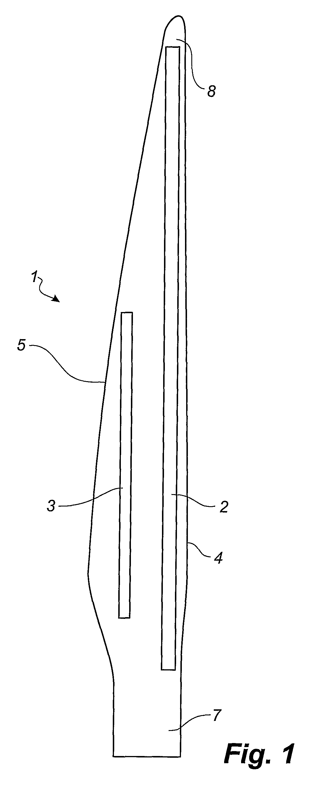
[0099]According to a given prototype of a LM61.5 wind turbine blade, the width of the main laminate differs in the longitudinal direction of the blade. The main laminate is approximately 850 mm wide and has a thickness of approx. 42 mm at the widest and thickest part, respectively. The width of the top hat also varies in the longitudinal direction of the blade and is approximately 360-370 mm at the widest part and 150 mm at the slimmest part.

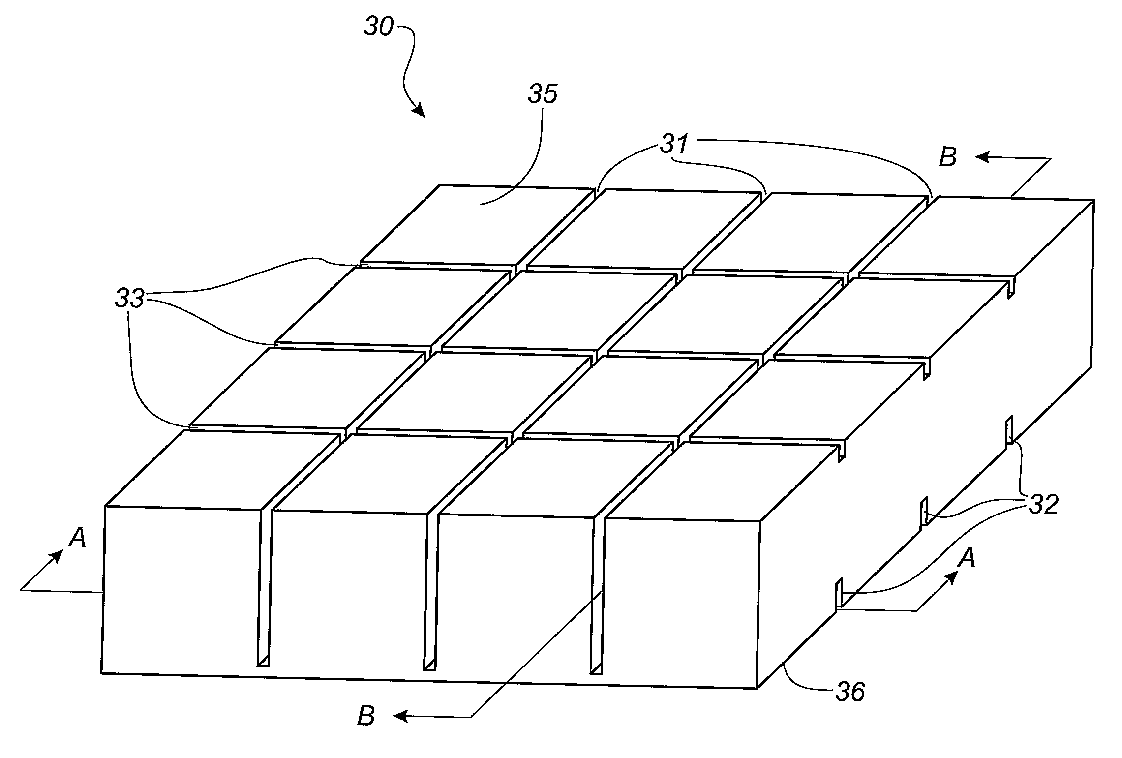
[0100]The core blocks have the following dimensions: w=1-1.2 mm, d=30 mm, h2=2.5+ / −0.5 mm, α=14 degrees, and t=1 mm. The core blocks have varying thickness h, and therefore the height of the first grooves is also varying. The overlap between the first grooves and the second grooves are equal to h2 minus t and is thereby 1.5-2.0 mm.

[0101]The examples have been described according to preferred embodiments. However, the invention is not limited to these embodiments. For example, the width and height of the individual grooves as well as the distance...


PUM

PropertyMeasurementUnit
distanceaaaaaaaaaa
distanceaaaaaaaaaa
distanceaaaaaaaaaa

Abstract

A use of a core block for an impregnation process as well as a composite structure comprising such a core block is described. The core block has a first surface and a second surface, and a number of first grooves is formed in the first surface of the core. Furthermore, a number of second grooves is formed in the second surface of the core. The first grooves have a first height (h1) and a bottom, and the first grooves and the second grooves are part of a resin distribution network formed in the core block. The distance (t) between the bottom of the first grooves and the second surface of the core block is of such a size that the core block is flexible along the first grooves. Additionally, the sum of the first height and the second height is larger than the thickness of the core block, and at least one of the first grooves in the first surface of the core block crosses at least one of the second grooves in the second surface of the core block.

Description

TECHNICAL FIELD[0001]The invention relates to a use of a core block for a resin impregnation process, such as vacuum assisted resin transfer moulding, and a method of forming a composite structure as well as a composite structure obtainable via the method.BACKGROUND[0002]Thus the invention relates to a method for producing fibre composite structures and composite structures obtained by means of VARTM (vacuum assisted resin transfer moulding), where liquid polymer, also called resin, is filled into a mould cavity, in which fibre material priorly has been inserted, as a vacuum is generated in the mould cavity hereby drawing in the polymer. The polymer can be thermoset plastic or thermoplast.[0003]Vacuum infusion or VARTM is a process used for moulding fibre composite mouldings, where uniformly distributed fibres are layered in one of the mould parts, the fibres being rovings, i.e. bundles of fibre bands, bands of rovings or mats, which are either felt mats made of individual fibres or...

Claims


Application Information

Patent Timeline
Patent Type & Authority Applications(United States)
IPC IPC(8): B32B7/02B29C33/76B29C45/02B29C47/02B29C48/76
CPCB29C70/443B29C70/547B29L2031/085F03D1/0675Y10T428/2495Y10T428/24496Y10T428/24612Y10T428/2457Y10T428/24479Y02E10/721Y02E10/72Y02P70/50B05B3/001B05B3/1092
Inventor MIKKELSEN, TOMMYSTAGE, MORTEN
Owner LM GLASSFIBER
Why Eureka
Try Eureka