
Fast Response Temperature Sensors

a temperature sensor and fast technology, applied in the direction of instruments, thermometers using value differences, heat measurement, etc., can solve the problems of increasing operator time, complex temperature measurement of fluid body, high accuracy of temperature measurement, etc., to reduce temperature response time, accurate and reliable temperature is quickly obtained, and the effect of quickly and accurately calculating ambient fluid temperatur

Active Publication Date: 2019-07-18
INSITU INC
View PDF0 Cites 3 Cited by
  • Summary
  • Abstract
  • Description
  • Claims
  • Application Information

AI Technical Summary

Benefits of technology

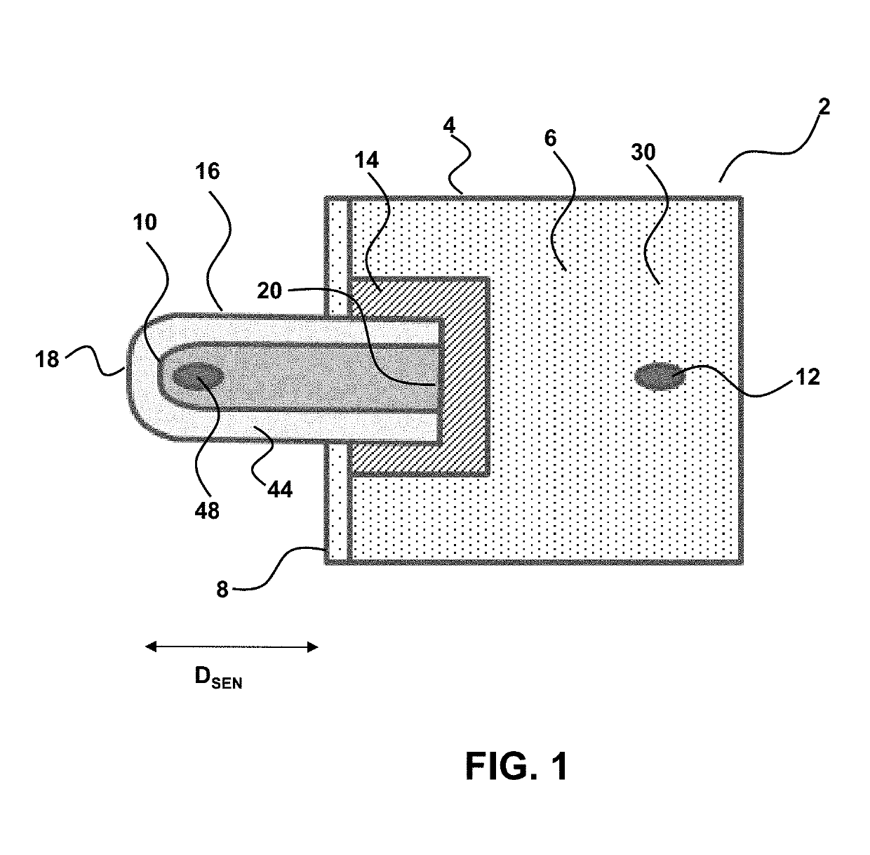
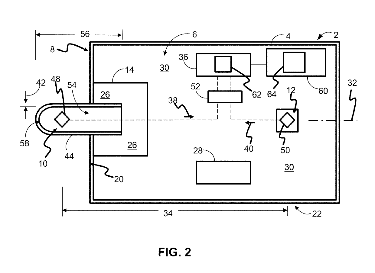
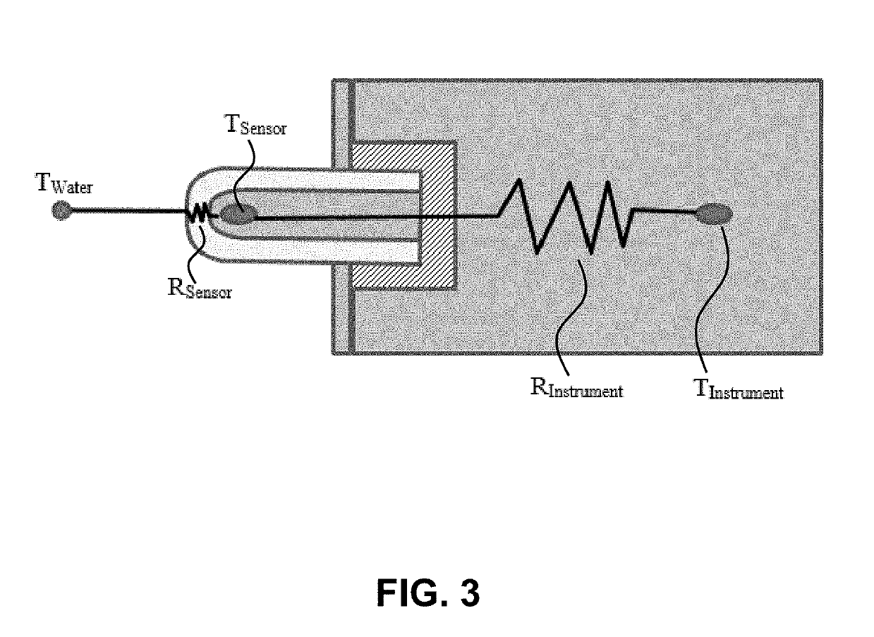
The patent describes a special temperature probe that can quickly and accurately measure liquid temperature. This is achieved by positioning a temperature sensor in a way that minimizes its contact with other parts of the device, such as power sources and electronics. This allows for a quick temperature measurement that is reliable and accurate. The temperature probe may also have multiple sensors to account for the impact of the device or probe on the surrounding fluid temperature and the heat within the device or probe. Overall, this technology improves the speed and accuracy of temperature measurements.

Problems solved by technology

Accurate temperature measurement of a fluid body is often complicated by the thermal effect of the sensor itself when immersed in the fluid.
For example, an instrument taken from a hot environment (e.g., inside a vehicle on a warm day into relatively cold water), will initially yield highly inaccurate temperature measurement.
A high response time results in inefficiencies, including arising from increased operator time as they await temperature stabilization.
This can give good results and take temperature stabilization down to a couple of minutes, but such conventional sonde temperature sensors take up a lot of space and tend to be more prone to bending and breaking.
Elongated temperature sensors also are hard to use with modern wiper cleaning systems.

Method used


Image

  • Fast Response Temperature Sensors
  • Fast Response Temperature Sensors
  • Fast Response Temperature Sensors

Examples


Embodiment Construction

[0063]In general, the terms and phrases used herein have their art-recognized meaning, which can be found by reference to standard texts, journal references and contexts known to those skilled in the art. The following definitions are provided to clarify their specific use in the context of the invention.

[0064]“Distal” and “proximal” refers to directions that are toward or away from an instrument body. For example, the temperature sensor for measuring liquid temperature, such as water temperature, is said to distally located, on or toward a distal sensing end. The temperature sensor used to measure the probe temperature is said to be located proximally to the fluid-measuring temperature sensor.

[0065]“Thermal barrier” refers to a material that is a thermal insulator and positioned so as to reduce heat flow from one region to a second region. “Thermally isolate” refers to the position of a thermal barrier between components, so that heat transfer between components is retarded. For ex...


PUM


Abstract

Provided herein is a differential temperature sensor which utilizes multiple temperature sensors to quickly and accurately calculate ambient fluid temperature with a reduced response time. The provided systems and methods utilize a first fluid temperature sensor and a second probe temperature sensor to account for the thermal impact of the device on the ambient fluid temperature and the effect of heat within the device, or temperature difference between the probe and fluid temperature, on the first fluid temperature sensor measurement.

Description

CROSS-REFERENCE TO RELATED APPLICATIONS[0001]This application claims the benefit of and priority to U.S. Provisional Patent Application No. 62 / 619,009 filed Jan. 18, 2018, which is incorporated by reference herein in its entirety.BACKGROUND OF INVENTION[0002]Fluid monitoring and analysis plays a key role in a variety of industries including aquaculture, oil and gas, mining, environmental analysis or any industry in which fluid parameters play a role in design or operations. Temperature is often an important parameter for a variety of applications and analyses.[0003]Accurate temperature measurement of a fluid body is often complicated by the thermal effect of the sensor itself when immersed in the fluid. For example, an instrument taken from a hot environment (e.g., inside a vehicle on a warm day into relatively cold water), will initially yield highly inaccurate temperature measurement. To compensate for the thermal differences between the sensor and fluid, and any effect caused by ...

Claims


Application Information

Patent Timeline
IPC IPC(8): G01K13/02F01D17/08
CPCG01K13/02F01D17/085G01K2013/026F05D2260/84F05D2260/231G01K7/427G01K13/026G01K3/14G01K7/22G01K1/18G01K7/42
Inventor KIMBELL, BENJAMINSCOTT, ELIJAH LYLEBALTZ, NATHAN T.
Owner INSITU INC
Learn More