Capacitive touchscreen mirror device and mehtod of manufacturing

a capacitive touchscreen, mirror device technology, applied in the field of mirrors, can solve the problems of negating the function of capacitive sensors, difficult to replicate the mirror experience, and relatively inconvenient operation of touch technologies, so as to achieve reliable position detection, no loss or degradation of functions, and minimal or no loss of sensing capability.

Active Publication Date: 2019-07-18
KONINKLJIJKE PHILIPS NV
View PDF6 Cites 1 Cited by
  • Summary
  • Abstract
  • Description
  • Claims
  • Application Information

AI Technical Summary

Benefits of technology

[0019]The inventors have found that, when the proposed separate metal islands or partitions of the reflective metal layer are equal to or smaller than the capacitive sensing areas, there is minimal or no loss of sensing capability. In practice, for human-finger operation, this implies that the separate metal islands are preferably equal to or smaller than a human fingertip to have no loss or degradation of function for the touchscreen panel. Therefore, in an embodiment, the separate metal islands or partitions have a maximum dimension, seen in a direction parallel to the mirror surface, of twelve millimeters or less, e.g. one centimeter. Such a maximum dimension of the separate metal islands enables a reliable detection of the position of a human fingertip on the mirror surface. Alternatively, when the capacitive sensor comprises a capacitive sensor grid, said maximum dimension may also be related to a resolution of the capacitive sensing elements of the capacitive sensor grid. E.g. the separate metal islands may have a maximum dimension twice as large as the resolution of the capacitive sensor grid, preferably a maximum dimension equal to or less than the resolution of the capacitive sensor grid. For example, the capacitive sensor grid may have a resolution of less than one centimeter. On the other hand, the separate metal islands of the reflective metal layer are preferably large enough to provide a sufficiently large total reflective surface area of the mirror surface, e.g. compared to the total surface area of the separation lines. Accordingly, the separate metal islands preferably have a minimum dimension, seen in a direction parallel to the mirror surface, of at least one millimetre, e.g. more than half a centimeter. For example, a typical surface area of the separate metal island or partition can be about twelve by twelve millimeters.
[0020]To create sufficient mirror-like appearance, it was found that the metal layer of the mirror surface preferably has a reflectivity of at least forty, and preferably at least fifty percent (i.e. for perpendicularly incident light in the visible wavelength range). Also other ranges are possible, e.g. a touch mirror device may have up to hundred percent reflectivity and very little or no transmission. For example, the display device can be omitted. At the same time, the reflectivity of the metal layer can also affect the amount of transmitted light coming from the display arranged behind the mirror surface. Accordingly, it is preferable that the reflectivity of the metal layer of the mirror surface does not exceed eighty percent, e.g. has a value between fifty and seventy percent, to avoid excessive losses of the display light transmitted through the mirror surface. For example, the metal layer may have a layer thickness between 0.1 and 50 micrometers, preferably between 1 and 10 micrometers.
[0021]The mirror surface can be provided on an optically transparent substrate, i.e. with a partitioned metal layer comprising separate metal island provided on the substrate. For example a glass or PMMA substrate can be provided with an aluminum or silver coating that is divided or partitioned into separated metal islands. The combination of a glass substrate and an aluminum layer is preferred in view of an improved transparency and relatively low costs. Furthermore, this combination may also provide an improved optical mirror performance, e.g. with respect to fidelity of the image with a low degree of distortions and defects (in other words, a high modulation transfer function). The substrate can be separately produced and mounted on an existing touchscreen panel display. Alternatively, the metal layer may be directly applied to the front side of the touchscreen panel display. Preferably, a transparent protective layer is applied on an outer surface of the device to protect the metal layer from damage. The protective layer can also be formed by the substrate on which the metal layer is applied, e.g. by arranging the metal layer between the (glass) substrate and the touchscreen panel. The touchscreen panel may also have its own protective (non-conductive) layer.

Problems solved by technology

However, it is difficult to replicate the mirror experience, e.g. depth, using a computer screen.
However, these touch technologies are relatively intrusive and not so easy to operate.
However, these metallic layers are also electrically conductive and therefore considered unsuitable in combination with capacitive sensors arranged behind the mirror surface.
In particular, the presence of such a conductive layer may negate the function of the capacitive sensors.
It is noted in the prior art that the known apparatus may suffer from cross-talk when multiple touch areas are intended.
However this may detract from a visual appeal of the mirror surface and only allow static touch controls.

Method used


Image

  • Capacitive touchscreen mirror device and mehtod of manufacturing
  • Capacitive touchscreen mirror device and mehtod of manufacturing
  • Capacitive touchscreen mirror device and mehtod of manufacturing

Examples


Embodiment Construction

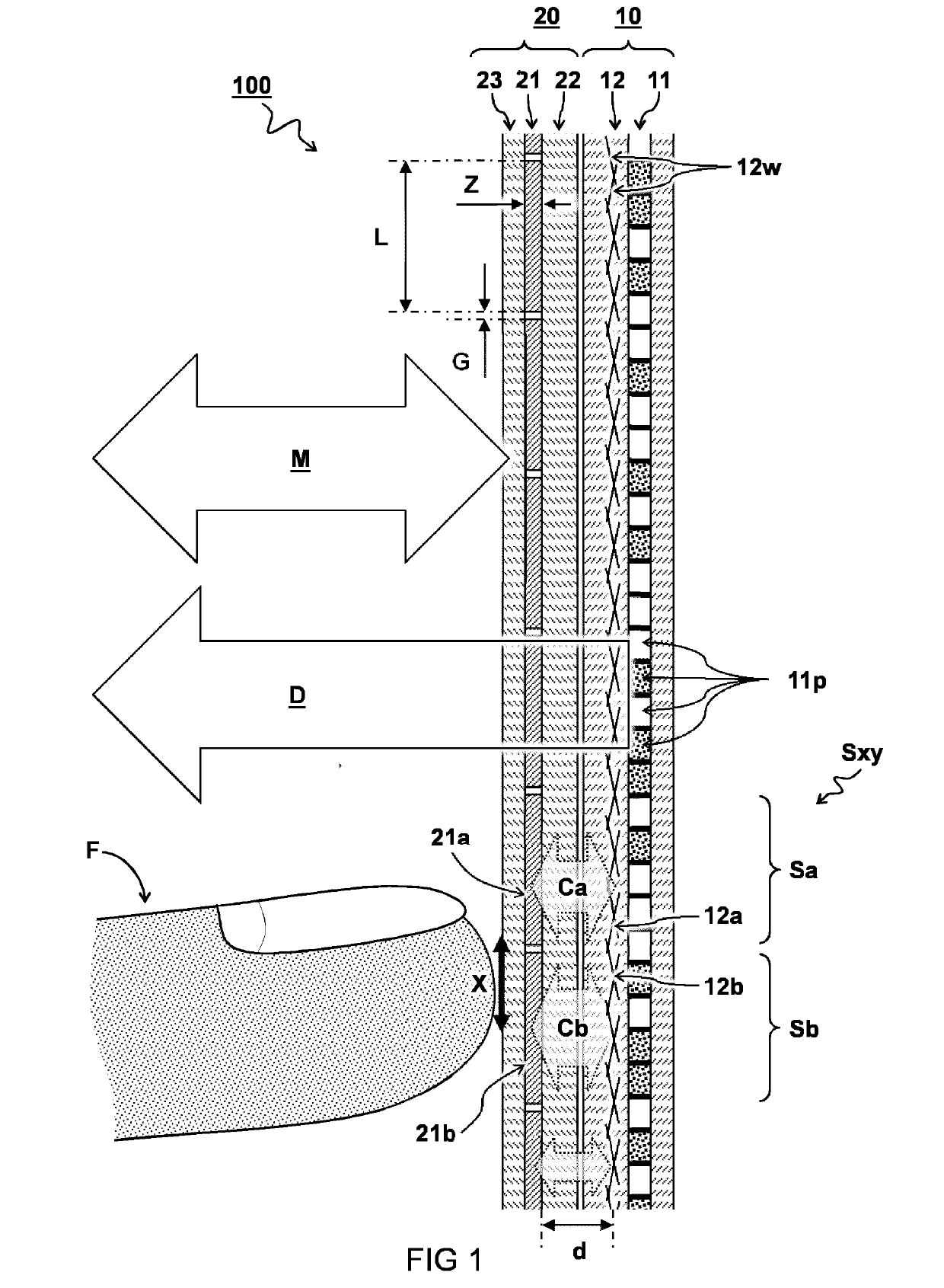
[0032]The present invention relates to a mirror device that provides additional user-interface functionality. In particular, a method to combine a metallic mirror surface with capacitive touchscreen functionality is described. The mirror device comprises a conventional thin metallic layer, for example of aluminum or silver, to provide the mirroring function. The mirror device further comprises a touchscreen to provide user-interface functionality. The touchscreen may have additional display functionality as is known in the art.

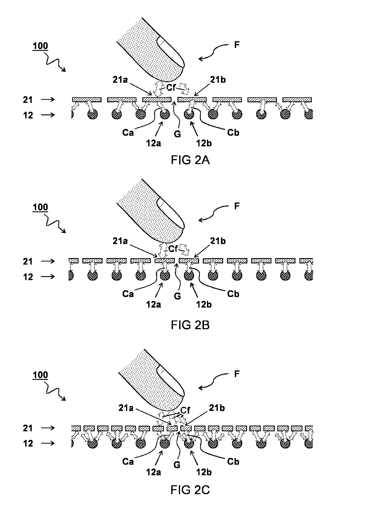
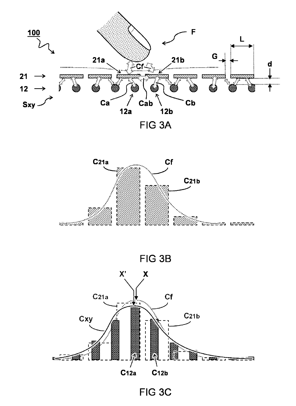
[0033]Generally, touchscreen displays can include a capacitive sensor grid that determines the presence or the location of an object such as a finger proximate to the sensor grid. Signals sensed by the capacitive sensor grid may change with the presence and location of a fingertip relative to the sensor grid. For example, the capacitive sensor grid may comprise a matrix of rows and columns of electrodes that detect changes in capacitive coupling caused by the ...


PUM


Abstract

Touchscreen mirror device (100) comprising a touchscreen panel (10) and a mirror surface (20). The touchscreen panel (10) comprises a grid of capacitive sensors (12) for detecting a position of an input object such as a fingertip (F) near the touchscreen panel (10). The mirror surface (20) is configured to at least partially reflect a mirror image (M) at a front side of the mirror surface (20). The mirror surface (20) comprises a reflective metal layer (21) divided in separate metal islands (21a,21b) that are electrically isolated from each other by a single contiguous gap (G) for allowing the capacitive sensor (12) to detect a position of the input object through the mirror surface (20).

Description

FIELD OF THE INVENTION[0001]The present invention relates to mirrors having an integrated touchscreen panel, in particular a capacitive touchscreen panel. The present invention further relates to a method of manufacturing such a capacitive touchscreen mirror device.BACKGROUND OF THE INVENTION[0002]Within the domain of personal care, e.g. shaving and grooming, so-called “magic mirrors” form a relatively new concept. With such magic mirrors, for example, information is displayed behind or on a mirror surface to enhance the standard mirror experience. In a particular implementation the magic mirror may use a camera image to display a mirror-image on a screen overlaid with enhancements. However, it is difficult to replicate the mirror experience, e.g. depth, using a computer screen. In another implementation the magic mirror uses a display screen behind a two-way (semi-transparent) mirror. In this implementation, for example, the mirror transmits an illuminated display image from a back...

Claims


Application Information

Patent Timeline
Patent Type & Authority Applications(United States)
IPC IPC(8): G06F3/044G06F3/042G02B5/08
CPCG06F3/044G06F3/0421G02B5/0808H03K17/9622H03K2017/9602H03K2217/96077
Inventor GODLIEB, ROBERTNIJDAM, JEROEN CHRISTIAN
Owner KONINKLJIJKE PHILIPS NV
Why Eureka
Try Eureka