Blind-spot eliminator side-view mirror

a technology of blind spot elimination and side view mirror, which is applied in the direction of mirrors, instruments, vehicle components, etc., can solve the problems of affecting vision, affecting the safety of drivers, and affecting the effect of distance perception, so as to improve the effect of fov, minimal or no loss of distance perception, and novel, inexpensive methods and devices

Active Publication Date: 2013-08-29
FURLOW JR LEONARD T
View PDF1 Cites 5 Cited by
  • Summary
  • Abstract
  • Description
  • Claims
  • Application Information

AI Technical Summary

Benefits of technology

[0013]The subject invention addresses the above described disadvantages associated with planar and spherically-curved mirrors by providing the advantage of an increased FOV with minimal or no loss of distance perception. In particular, the subject invention provides novel, inexpensive, and highly effective methods and devices for increasing the FOV of a vehicle driver.

Problems solved by technology

Despite the many design advances made to vehicles, most on the road today do not provide drivers with a full 360° field of view (FOV).
During the time a vehicle passing or being passed is not in view it may constitute a danger because the driver may be unaware of its presence or misjudge its distance.
In many vehicles the door frames and the body sections behind the back windows interfere with vision in the standard front windshield-mounted mirror.
However, spherically-convex mirrors provide a flawed view because an object reflected therein often appears significantly smaller.
Thus, the increased FOV provided by the spherically-convex mirror is obtained at the cost of a reduction in image size, which, if not accounted for by a driver, can cause a dangerous misjudgment of distance.

Method used


Image

  • Blind-spot eliminator side-view mirror
  • Blind-spot eliminator side-view mirror
  • Blind-spot eliminator side-view mirror

Examples


Embodiment Construction

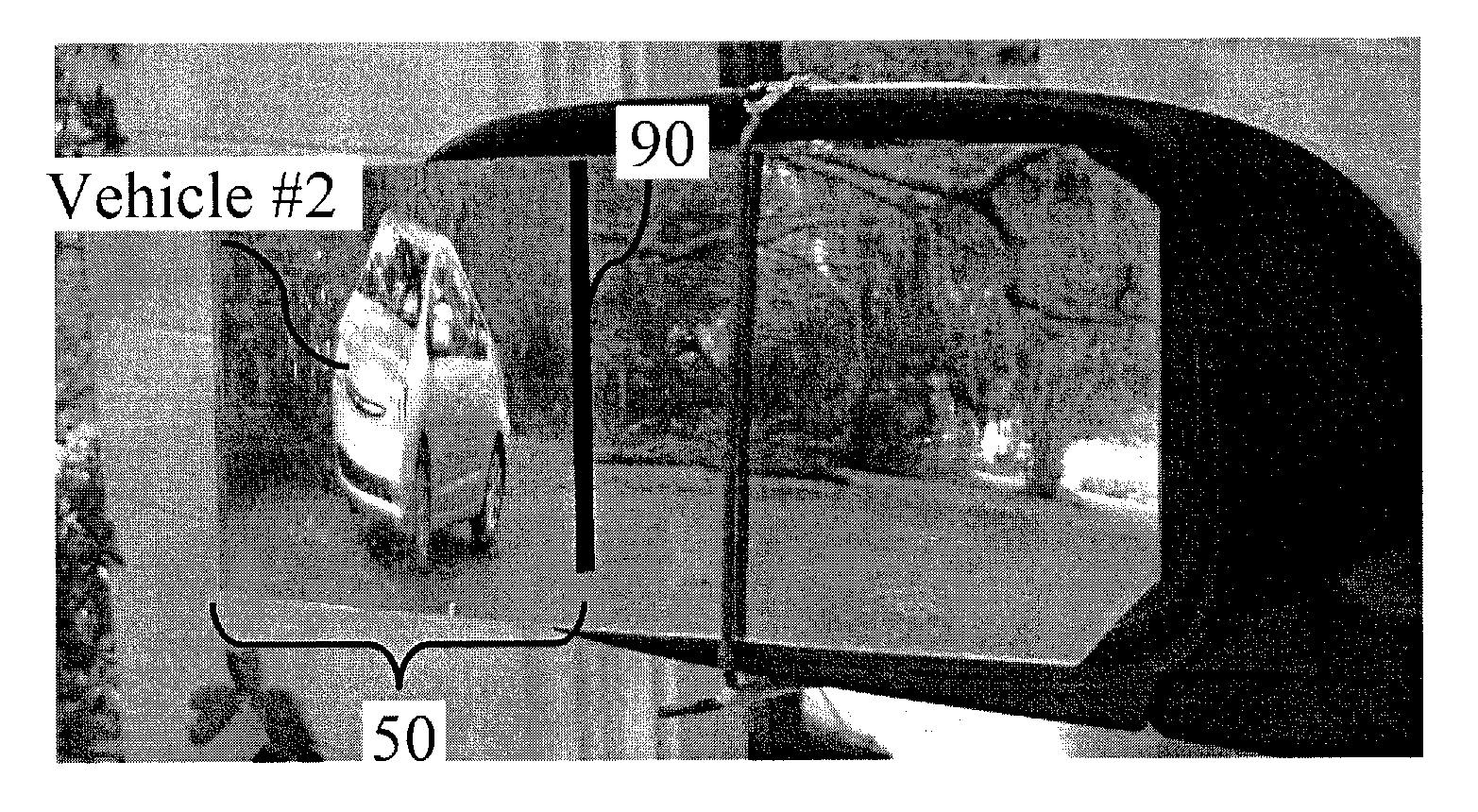
[0030]The subject invention pertains to mirrors for increasing visibility. More specifically, the subject invention provides vehicle mirrors capable of providing increased field of view (FOV). In certain embodiments, the mirrors of the subject invention provide a FOV that can include the area proximal to and to the rear of a vehicle to a point where a vehicle in an adjacent lane appears in a driver's lateral vision. Still more specifically, the subject invention provides side-view or “wing” mirrors for vehicles that will allow a FOV that is both behind and lateral (i.e., to the sides of) a vehicle. With these embodiments, objects that are adjacent to a first vehicle, such as a second or adjacent vehicle, that may be passing on either side of, or otherwise moving around, the first vehicle, will remain in mirror view until they are within the approximate lateral view of the vehicle driver.

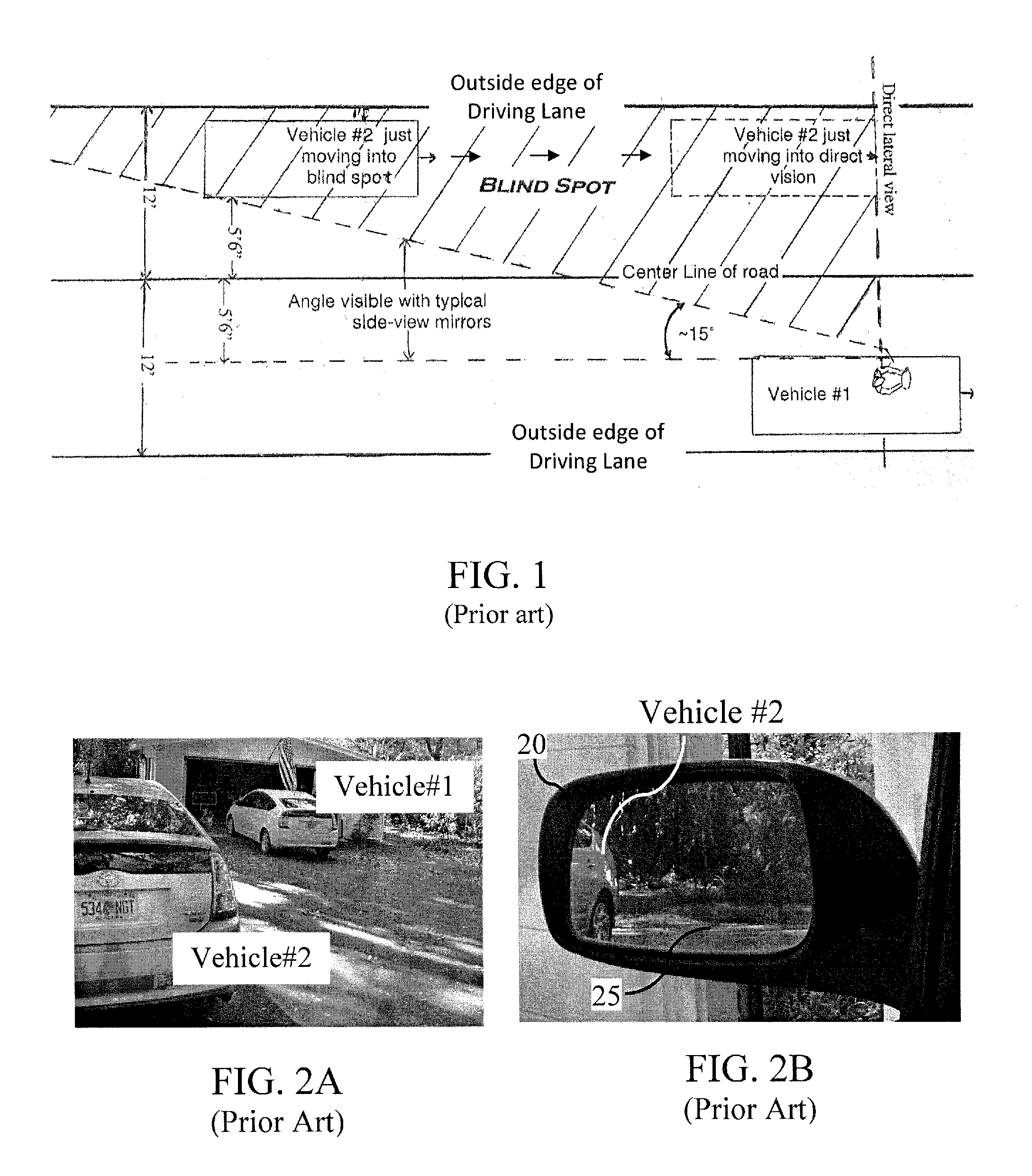
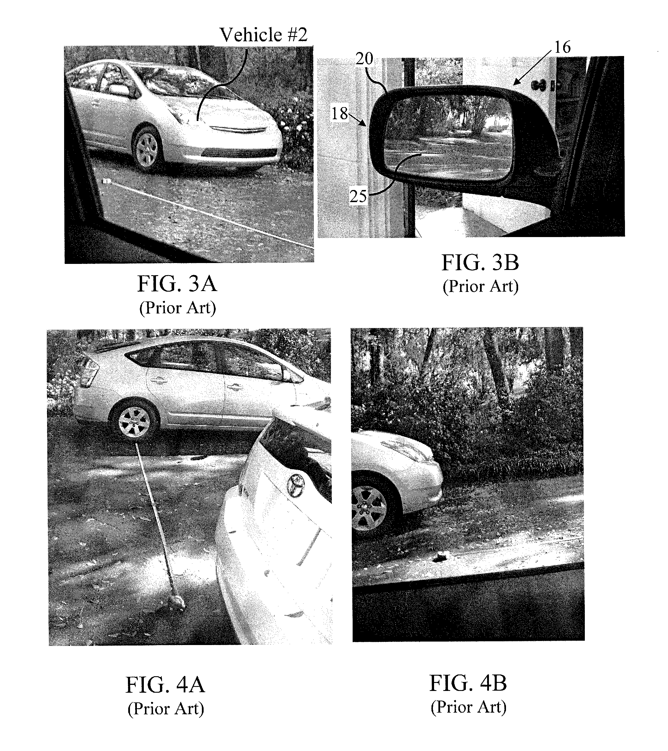
[0031]The mirrors of the subject invention are particularly useful when operating vehicles on mul...


PUM


Abstract

The subject invention provides vehicle mirrors that increase the field of view on one or both sides of a vehicle to bring into view the area behind and lateral to the standard mirror's field of view (the “blind spot”). One embodiment utilizes a flat-plane mirror in conjunction with a horizontally-convex portion at one side. The purpose of the horizontally-convex vertically-straight design is to maintain the vertical dimension of the image to retain proper perception of distance. Utilizing the mirrors of the subject invention, a vehicle driver is able to see directly behind and to the side of the vehicle with maintenance of distance perception. The horizontally-convex portion increases the driver's field of view along the rear and side of a vehicle eliminating or reducing blind spots.

Description

CROSS-REFERENCE TO RELATED APPLICATION[0001]The present application claims the benefit of U.S. Provisional Application Ser. No. 61 / 604,835, filed Feb. 29, 2012, which is hereby incorporated by reference herein in its entirety, including any figures, tables, or drawings.BACKGROUND OF INVENTION[0002]Despite the many design advances made to vehicles, most on the road today do not provide drivers with a full 360° field of view (FOV). During the time a vehicle passing or being passed is not in view it may constitute a danger because the driver may be unaware of its presence or misjudge its distance.[0003]While the windows of vehicles generally provide sufficient direct front and lateral views, most vehicles include side-view mirrors to provide additional rearward FOV. However, most side-view minors have a characteristic “blind-spot” between the area lateral to the side-view minor's field and behind the driver's direct lateral vision. As an adjacent vehicle approaches to pass in an adjace...

Claims


Application Information

Patent Timeline
Patent Type & Authority Applications(United States)
IPC IPC(8): B60R1/08
CPCB60R1/081B60R1/082
Inventor FURLOW, JR., LEONARD T.
Owner FURLOW JR LEONARD T
Why Eureka
Try Eureka