Power supplies for projectiles and other devices

a technology for projectiles and power supplies, applied in the direction of cell components, cell components, electric fuzes, etc., can solve the problems of significant power requirements, and achieve the effect of reducing or minimizing wiring requirements

Inactive Publication Date: 2010-10-14
RASTEGAR JAHANGIR S +1
View PDF1 Cites 10 Cited by
  • Summary
  • Abstract
  • Description
  • Claims
  • Application Information

AI Technical Summary

Benefits of technology

[0007]An objective of the methods and devices of the present invention is the development of power generation devices for use on various guided and smart munitions. Depending on each specific application, one or a combination of such power generation devices can be utilized for optimal performance and minimal space and weight requirements.
[0008]Thus, a primary objective of the present invention is to provide novel methods and devices for electric power generation that can be readily integrated into the structure of the projectile with minimal or no loss of the intended functionality of the structure. As a result, all or a significant portion of the space required to house an equivalent power source can be saved. In addition, the power generation devices and their related components are better protected against high acceleration loads, vibration, impact loading, repeated loading and acceleration and deceleration cycles that can be experienced during transportation and loading operations.
[0011]The power generators are primarily integrated into the structure of the projectile as load bearing members to minimize the space requirements.
[0012]As load-bearing members, structurally integrated power generators would add minimal weight to the entire system.
[0017]Eliminate or minimize wiring requirements since the electronic, communications, sensory devices and many of the guidance and control actuation devices may be directly mounted on the structure of the projectile at the power generation site.

Problems solved by technology

The power requirement, however, becomes significant when the projectile has to be equipped with electric or smart materials based actuation devices for guidance and control, particularly if the projectile is required to become highly maneuverable over long traveling times and while traveling at relatively high speeds such as supersonic speeds.

Method used


Image

  • Power supplies for projectiles and other devices
  • Power supplies for projectiles and other devices
  • Power supplies for projectiles and other devices

Examples


Embodiment Construction

[0039]The methods and devices for power generation that utilize the available geometry of the projectiles and other devices and are essentially integrated into the structure of the projectile or other device will now be described in detail. The proposed devices, their various components, their general mode of operation, and their general characteristics are described. The devices are divided into two major categories. The first category includes those concepts in which the energy is derived primarily from the potential energy stored in certain medium or elements during the firing as the projectile is accelerated in a gun barrel. The second category includes those devices that utilize thermophotovoltaic materials, which are integrated into the structure of the projectile or other devices, on appropriate surfaces as relatively thin layers where they are used to convert radiated heat to electrical energy.

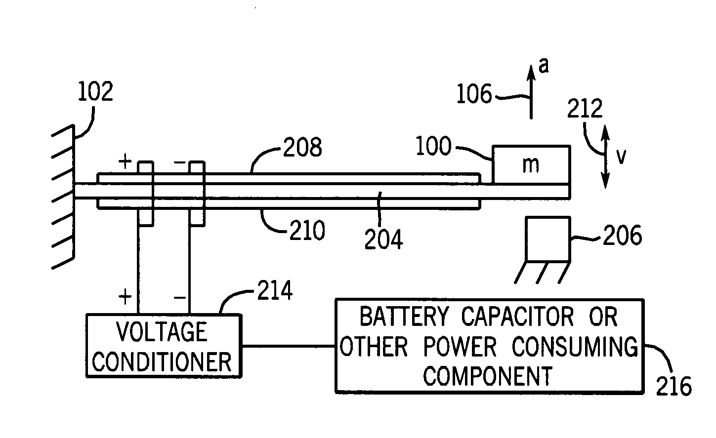
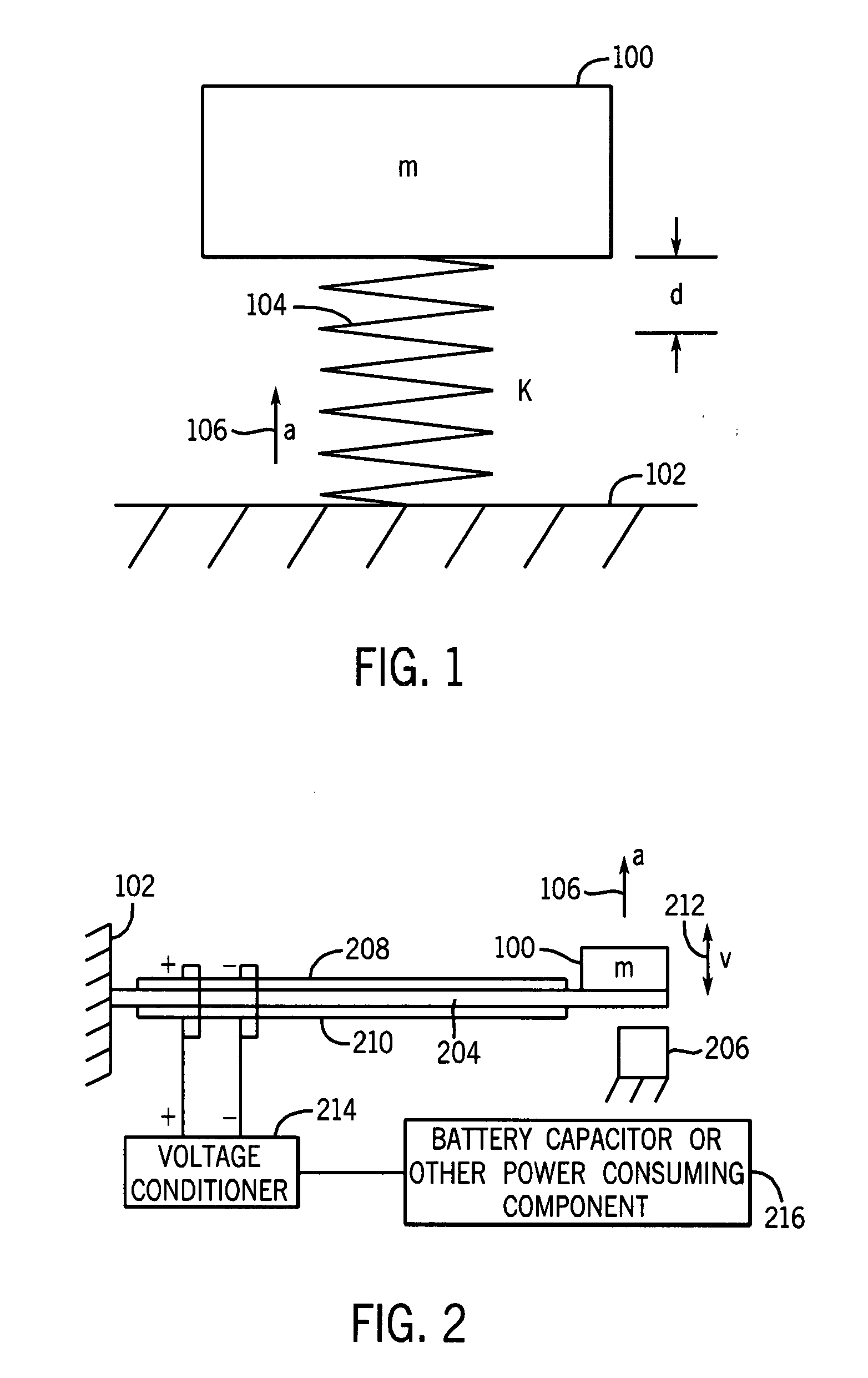
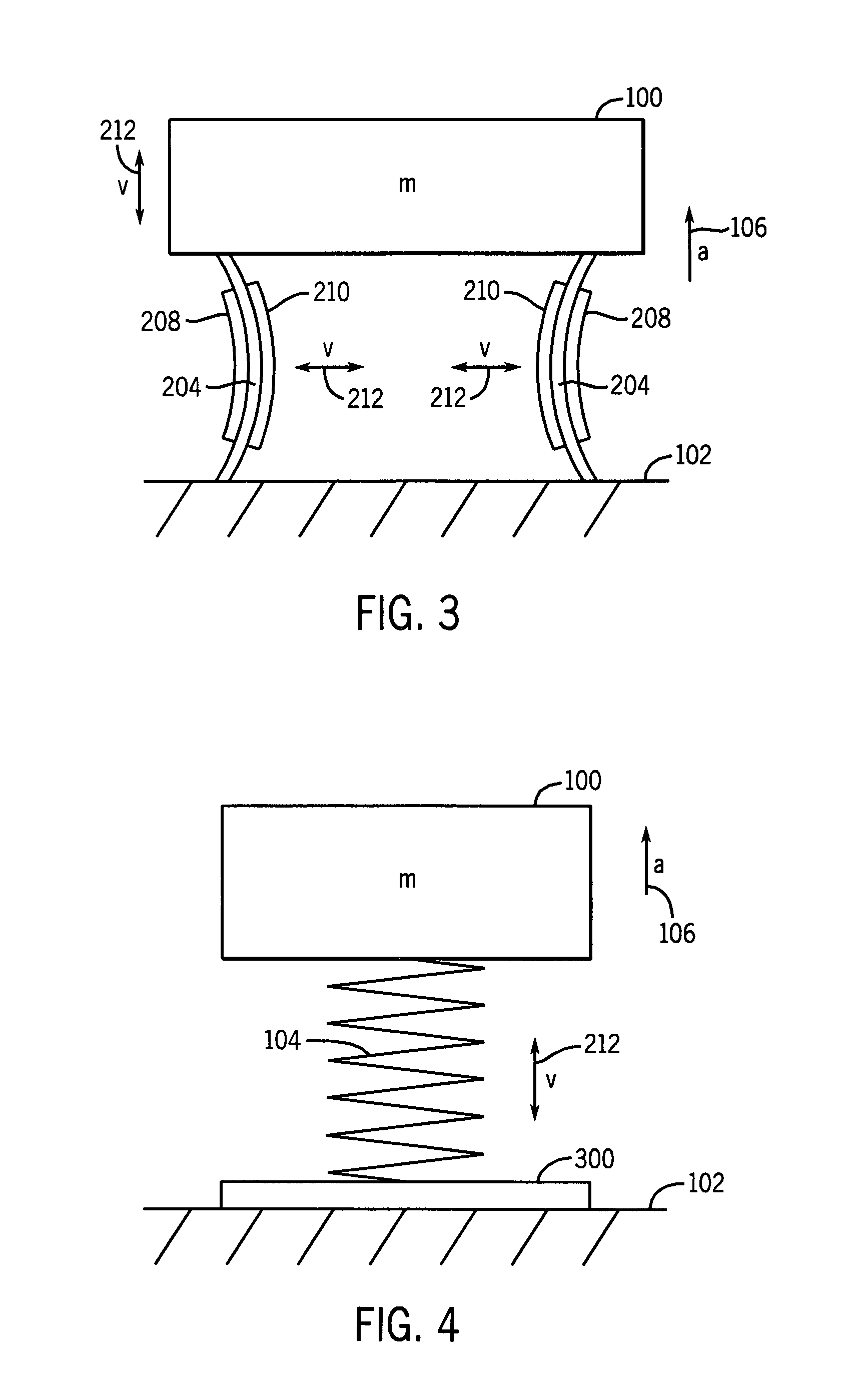
[0040]Consider an object 100 having a mass m attached to a moving platform 102 by ...


PUM

PropertyMeasurementUnit
weightaaaaaaaaaa
potential energyaaaaaaaaaa
stored potential energyaaaaaaaaaa

Abstract

A projectile including: at least one power consuming element, and a power supply which generates power from an acceleration of the projectile and supplies such power to the at least one power consuming element, the power supply including a device for storing potential energy upon the acceleration of the projectile and a device for converting the stored potential energy to electrical energy. Where the device for storing potential energy upon the acceleration of the projectile includes a movable mass and an energy storage device for storing energy upon the acceleration of the movable mass and the energy storage device is a chamber having a compressible fluid therein, the chamber being acted upon by the movable mass to reduce the volume of the chamber subsequent to acceleration of the movable mass.

Description

CROSS-REFERENCE TO RELATED APPLICATION[0001]This application is a divisional application of U.S. application Ser. No. 10 / 235,997 filed on Sep. 4, 2002 which claims priority to earlier filed U.S. provisional application Ser. No. 60 / 317,308 filed on Sep. 5, 2001, the entire contents of each of which are incorporated herein by their reference.BACKGROUND OF THE INVENTION[0002]1. Field of the Invention[0003]The present invention relates generally to power supplies, and more particularly, to power supplies for projectiles, which generate power due to an inherent characteristic of the projectile, such as its acceleration, spin, and / or heat generation.[0004]2. Prior Art[0005]All existing and future smart and guided projectiles and those with means of one-way or two-way communications with a command or tracking station or with each other require electric power for their operation. In addition, as munitions are equipped with the means of communicating their type and characteristics with the f...

Claims


Application Information

Patent Timeline
Patent Type & Authority Applications(United States)
IPC IPC(8): F42C11/00F42C11/02F42C11/04F41H11/02F41J2/00F42B10/14F42B12/34F42B12/46F42C15/40H01M2/02H01M2/10H01M10/40H01M12/06
CPCF41H11/02F41J2/00F42C15/40F42B12/34F42B12/46F42B10/14
Inventor RASTEGAR, JAHANGIR S.SPINELLI, THOMAS
Owner RASTEGAR JAHANGIR S
Why Eureka
Try Eureka