
Conformal power supplies

a power supply and uniform technology, applied in the field of power supplies, can solve the problems of long time-consuming and laborious, high vibration of projectiles, and one power source solution that is not practical and/or optimal for all current and planned future applications, and achieves the effect of long shelf li

Active Publication Date: 2006-10-10
OMNITEK PARTNERS LLC
View PDF2 Cites 5 Cited by
  • Summary
  • Abstract
  • Description
  • Claims
  • Application Information

AI Technical Summary

Benefits of technology

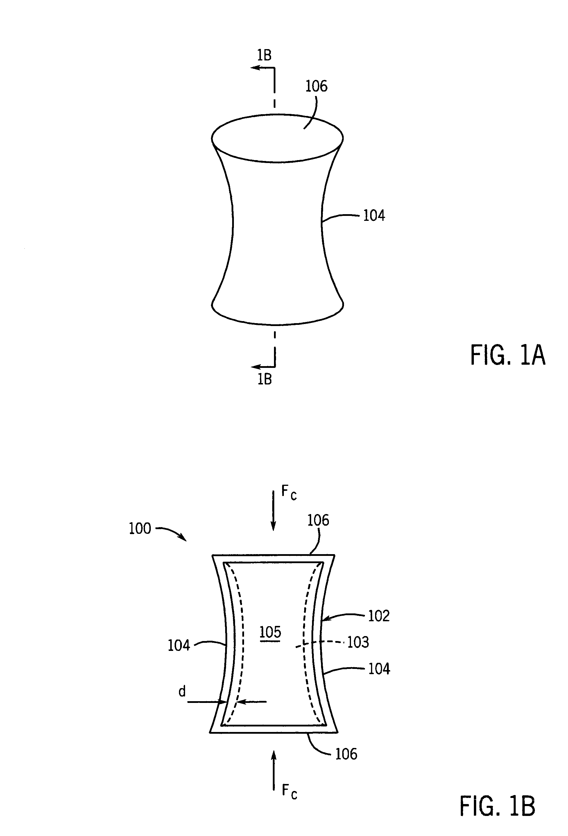
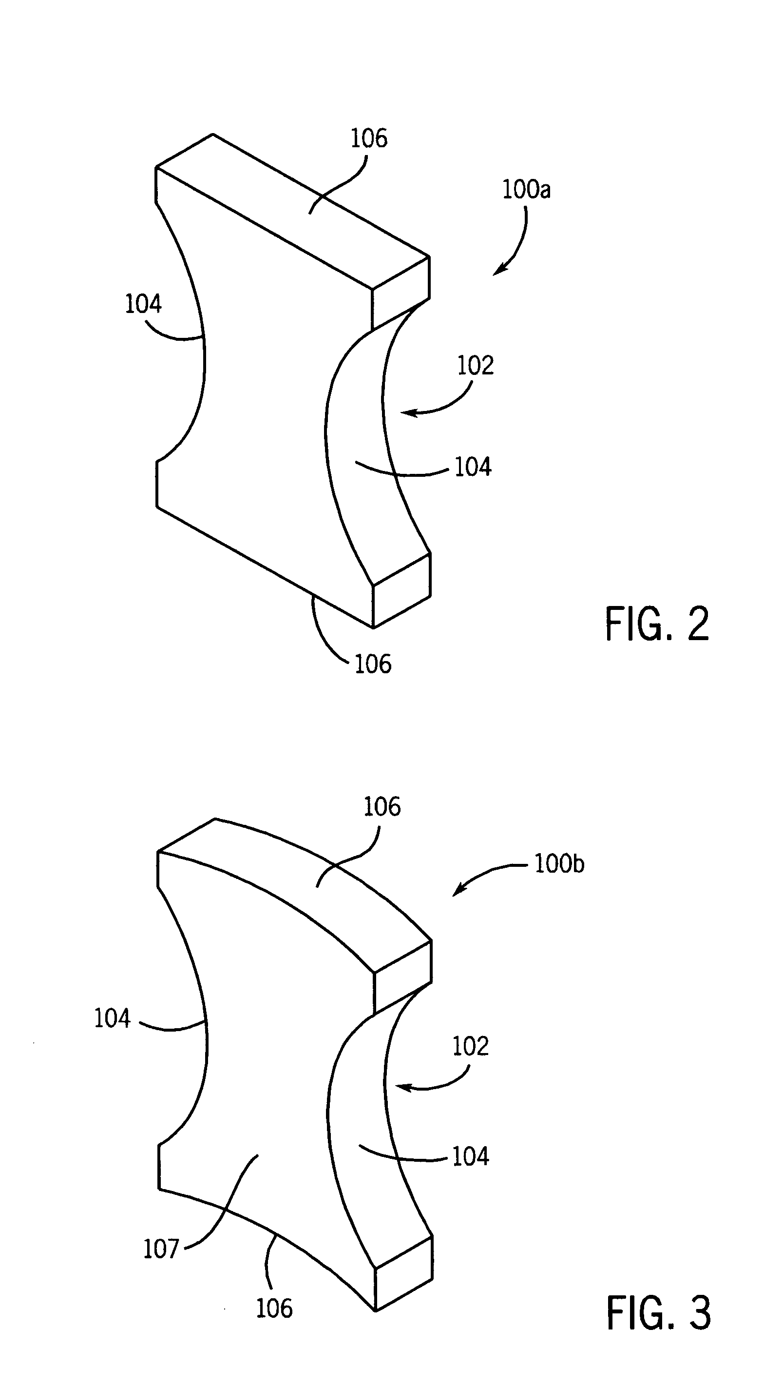
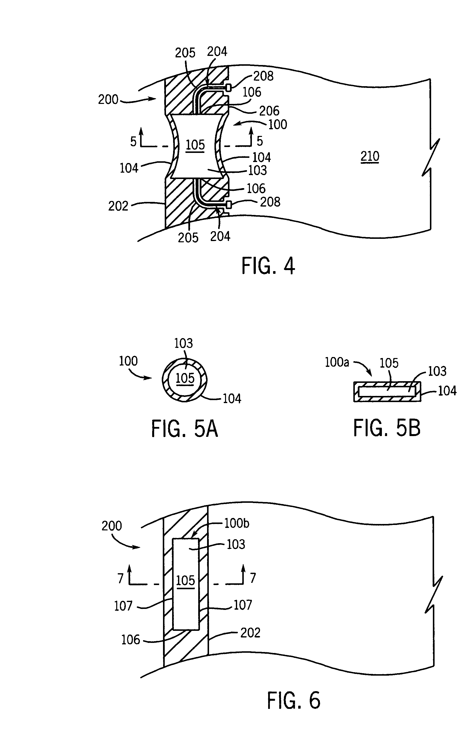
[0022]A primary objective of the present invention is to provide conformable power sources that can be integrated into the structure of the projectile or other device with minimal or no loss of the intended functionality of the structure. As a result, all or a significant portion of the space required to house the power source and the aforementioned components can be saved. In addition, the power sources and their related components are better protected against high acceleration loads, vibration, impact loading, repeated loading and acceleration and deceleration cycles that can be experienced during transportation and loading operations.
[0026]As load-bearing members, structurally integrated and conformal batteries would also add minimal weight to the entire system.
[0031]Eliminate or minimize wiring requirements inside the projectile or device since the structurally integrated and conformal batteries can be distributed throughout the system at the site of the load (sensors, communication electronics, actuation devices, etc.).
[0032]Include power sources with zero initial charge for safety, reliability and very long shelf life.

Problems solved by technology

As munitions are equipped with health monitoring and diagnostics capabilities, they would also require a low level of power supply for long periods of time.
As the result, one power source solution is not expected to be practical and / or optimal for all current and planned future applications.
In addition, such projectiles will be subject to high levels of vibration, impact type of loading, and certain amount of lower levels of repeated loading and acceleration and deceleration cycles as they are handled during transportation and loading.
As a result, a considerable amount of the available space has to be assigned to house the batteries and their related components.
In addition to the space requirements, one also faces problems related to reliability and survivability of the hardening components during the firing, proper operation at all times, deterioration during long periods of storage and the high cost of production and assembly into the projectile and related hardening efforts and testing.

Method used


Image

  • Conformal power supplies
  • Conformal power supplies
  • Conformal power supplies

Examples


Embodiment Construction

[0055]The novel power sources that are conformal to the available geometry and which are integrated into the structure of a projectile or other device will now be described in detail. The methods and devices of the present invention and their various components, their general mode of operation, and their general characteristics are provided. The methods and devices are generally divided into two major categories. The first category includes those methods and devices that are primarily based on the utilization of patented Structural Elements for integration of the power sources (batteries) into the structure of projectiles as load bearing members. The patented structural elements are described in U.S. Pat. No. 6,054,197 to Rastegar, the disclosure of which is incorporated herein by its reference. The second category includes those methods and devices that are integrated into the structure of the projectile or other device, primarily on the appropriate and / or available surfaces of the...


PUM

PropertyMeasurementUnit
surface areaaaaaaaaaaa
thicknessaaaaaaaaaa
thicknessaaaaaaaaaa

Abstract

A device including: a structure for housing or supporting at least one power consuming element; and a power supply integrated into the structure, the power supply being electrically connected to the at least one power consuming element for supplying power to the same.

Description

CROSS-REFERENCE TO RELATED APPLICATION[0001]This application claims priority to earlier filed U.S. provisional application Ser. No. 60 / 317,308 filed on Sep. 5, 2001, the entire contents of which is incorporated herein by its reference.BACKGROUND OF THE INVENTION[0002]1. Field of the Invention[0003]The present invention relates generally to power supplies, and more particularly, to batteries and power supplies, which are conformable to a structure or integrated into the structure itself.[0004]2. Prior Art[0005]All existing and future smart and guided projectiles and those with means of one-way or two-way communications with a command or tracking station or with each other require electric power for their operation. As munitions are equipped with health monitoring and diagnostics capabilities, they would also require a low level of power supply for long periods of time. The amount of power required for the proper operation of such smart and guided munitions or those equipped with heal...

Claims


Application Information

Patent Timeline
Patent Type & Authority Patents(United States)
IPC IPC(8): H01M2/28H01M50/541F41H11/02F41J2/00F42B10/14F42B12/34F42B12/46F42C15/40H01M10/40H01M12/06H01M50/209H01M50/213H01M50/247
CPCF41H11/02F41J2/00F42B10/14F42B12/34F42B12/46F42C15/40H01M2/02H01M2/0285H01M2/10H01M2/1066H01M6/36H01M12/06H01M2002/0205H01M50/209H01M50/247H01M50/213
Inventor RASTEGAR, JAHANGIR S.SPINELLI, THOMAS
Owner OMNITEK PARTNERS LLC
Learn More