Electrical connector

Active Publication Date: 2019-07-18
ADVANCED CONNECTEK INC
View PDF22 Cites 0 Cited by
  • Summary
  • Abstract
  • Description
  • Claims
  • Application Information

AI Technical Summary

Benefits of technology

[0007]The embodiments of the invention provide an electrical connector that effectively prevents d

Problems solved by technology

On current USB interfaces, since conductive metal conductors are spatially arranged to be very close to each other, capacitive coupling is inevitably increased in signal transmission, which increases disturbance in signal transmission and reduces stability in signal transmission.
Moreover, impedance mismatch disturbs signal transmission and meanwhile reduces stability in signal transmiss

Method used


Image

  • Electrical connector
  • Electrical connector
  • Electrical connector

Examples


Example

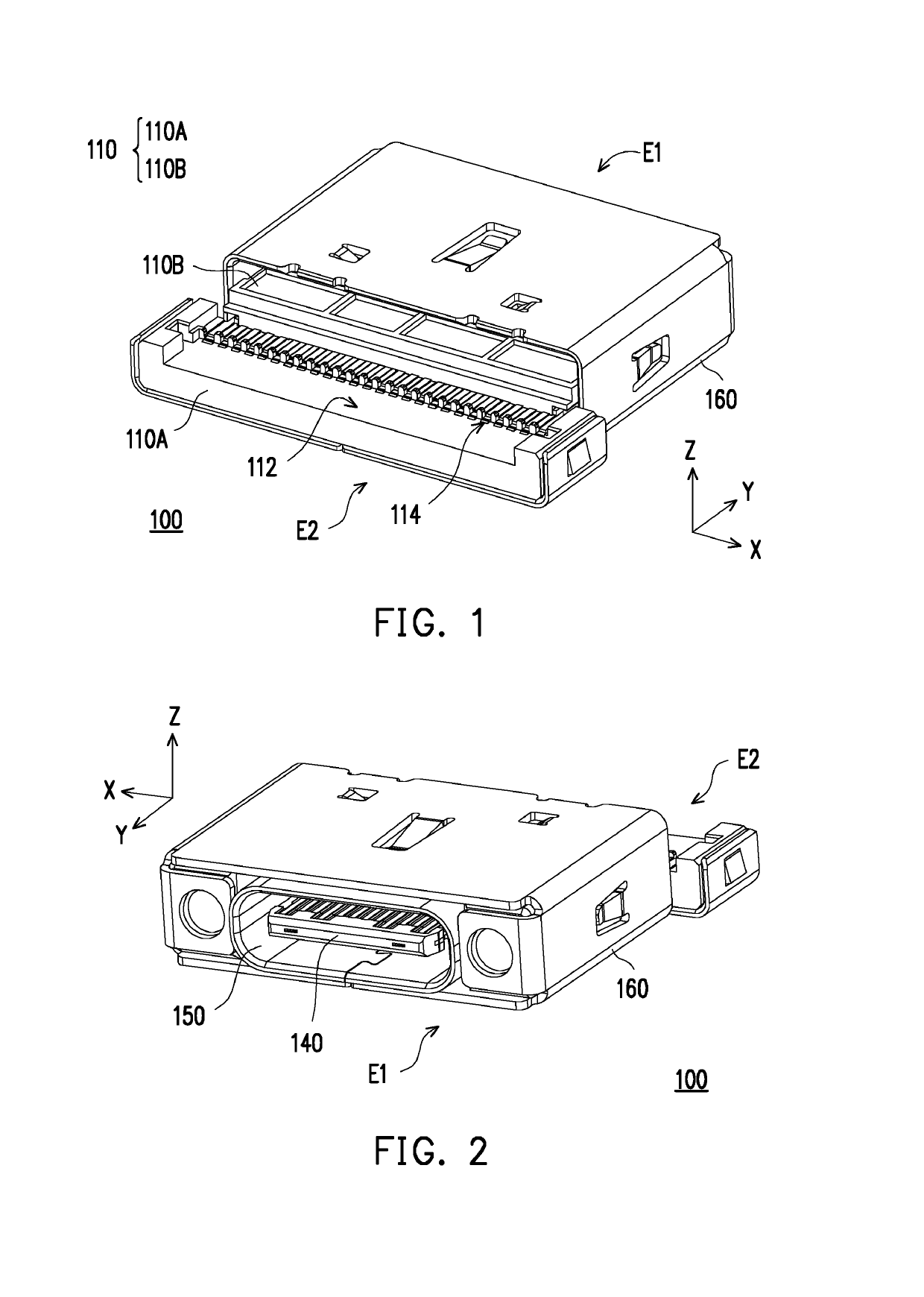
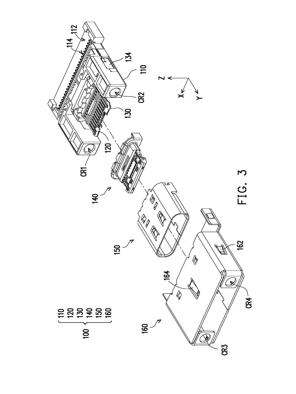
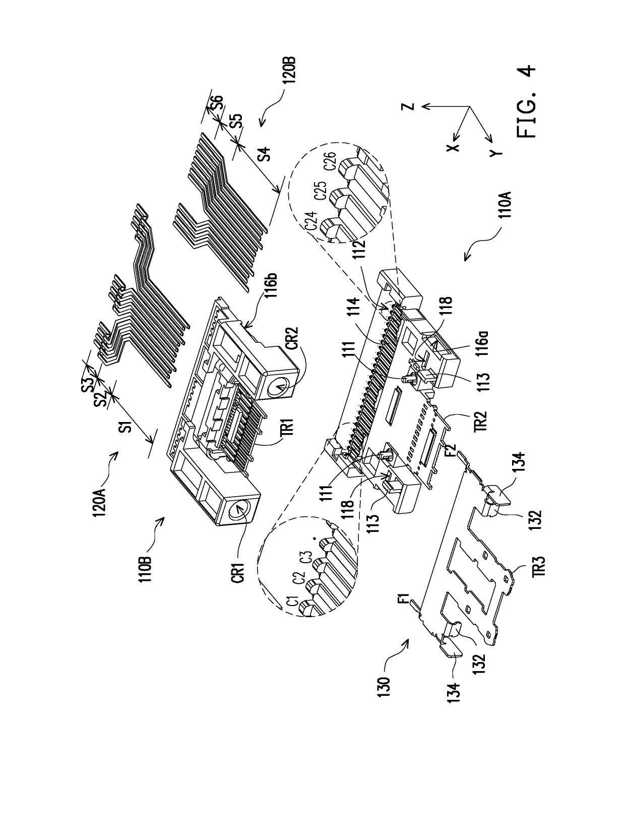
[0030]FIG. 1 and FIG. 2 respectively illustrate an electrical connector according to an embodiment of the invention from different viewing angles. FIG. 3 and FIG. 4 are respectively exploded views of different degrees illustrating the electrical connector of FIG. 2. A Cartesian coordinate axes X-Y-Z are also provided here to facilitate description of relevant components. Referring to FIG. 1 to FIG. 3 first, in the present embodiment, an electrical connector 100 is, for example, a USB Type-C connector and includes a base member 110, a plurality of first terminals 120, a sleeve member 140, a first shielding shell 160, and a second shielding shell 150, wherein the first terminals 120 are disposed in the base member 110, the sleeve member 140 is molded around a part of the base member 110, the second shielding shell 150 is fit around the sleeve member 140, and the first shielding shell 160 is fit around the base member 110.

[0031]Then, referring to FIG. 3 and FIG. 4, particularly, in FIG...


PUM


Abstract

An electrical connector including a base member and a plurality of first terminals disposed in the base member is provided. Each of the first terminals has an contact segment and an tail segment opposite to each other. The contact segments respectively belong to two different parallel planes, and the tail segments are located on a same plane. The first terminals form a plurality of terminal sets in the tail segments, and each of the terminal sets includes a ground terminal, a pair of super speed differential terminals, and a power terminal which are adjacent to each other and are sequentially arranged.

Description

CROSS-REFERENCE TO RELATED APPLICATION[0001]This application claims the priority benefit of Taiwan patent application serial no. 107200685, filed on Jan. 15, 2018. The entirety of the above-mentioned patent application is hereby incorporated by reference herein and made a part of the specification.BACKGROUND OF THE INVENTIONField of the Invention[0002]The disclosure relates to an electrical connector.[0003]Description of Related Art[0004]In recent years, as people's demands for the transmission rate and storage capacity become higher and higher, the USB 3.1 Super Speed+ specification of the USB transmission rate has been developed. Particularly, the new USB Type-C specification provides a maximum transmission rate as high as 10 Gbps and achieves a higher transmission rate when transmitting large-size files, thus effectively reducing a transmission time.[0005]As the transmission rate of a high speed transmission interface becomes significantly improved, conducting terminals are incre...

Claims


Application Information

Patent Timeline
IPC IPC(8): H01R13/6585H01R12/71H01R13/6597H01R12/70G06F13/42G06F13/40
CPCH01R13/6585H01R12/71H01R13/6597H01R12/7064G06F13/4282G06F13/4068G06F2213/0042H01R13/40H01R13/652H01R13/6591H01R12/721H01R13/6596
Inventor HOU, PIN-YUANTSAI, YU-LUNWANG, HSU-FENYEH, YU-CHAI
Owner ADVANCED CONNECTEK INC
Why Eureka
Try Eureka