

Connection device for transformer substation modules
- Summary
- Abstract
- Description
- Claims
- Application Information
AI Technical Summary
Benefits of technology
Problems solved by technology
Method used
Image

Examples
Embodiment Construction
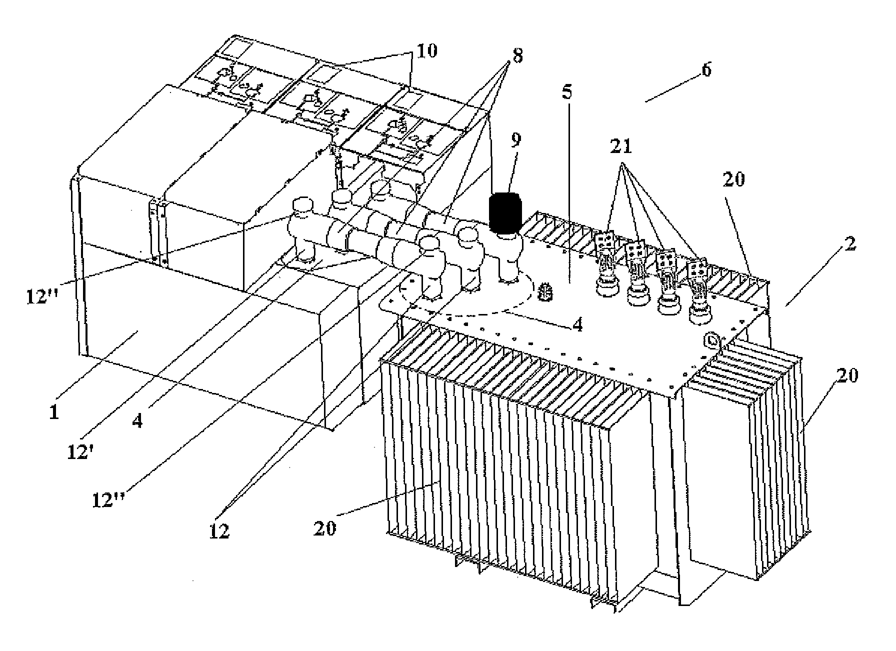
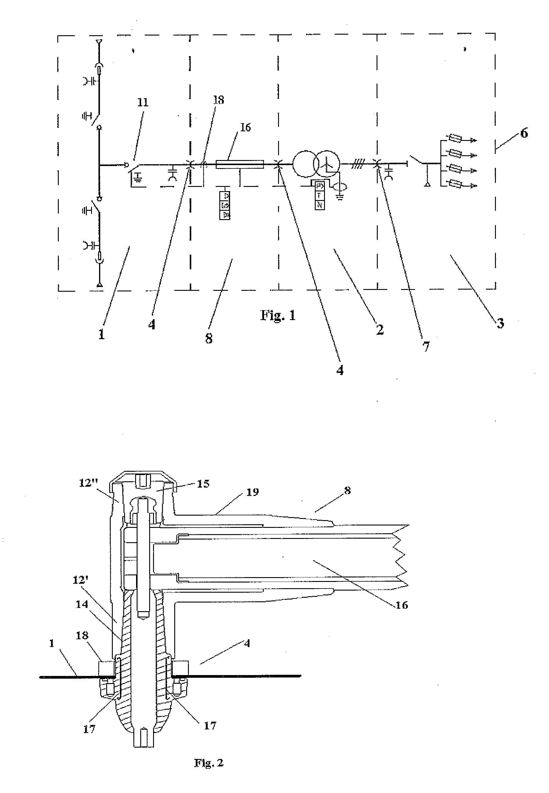
[0018]The present invention relates to a modular transformer substation, comprising at least high-voltage switchgear, a transformer and a low-voltage switchboard, such that since said transformer substation is modular, the modules making it up are standard and can be combined giving rise to different end solutions, each of said modules maintaining its own separate identity, such that it is possible to disassemble the high-voltage or low-voltage switch gear, each element being maintained in perfect use conditions.
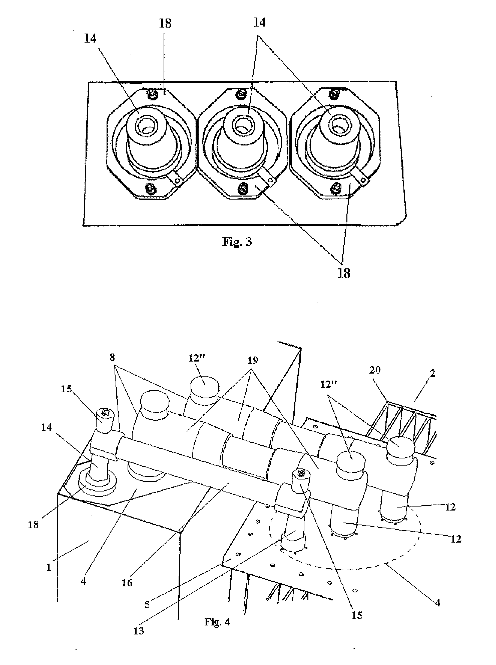
[0019]According to the present invention, the transformer is a conventional transformer, i.e., comprising cooling fins in its four side walls and an upper cover configured to allow a high-voltage electric connection between the transformer and the high-voltage switchgear and a low-voltage electric connection with the low-voltage switchboard.
[0020]The high-voltage electric connection between the high-voltage switchgear and the transformer, as well as the low-voltage electric ...
PUM
 Abstract
Description
Claims
Application Information