Eureka AIR delivers breakthrough ideas for toughest innovation challenges, trusted by R&D personnel around the world.

Inkjet head device for inkjet printers

a head device and inkjet printer technology, applied in printing and other directions, can solve the problems of troublesome disassembly, assembly and maintenance of components, and achieve the effect of convenient assembly or maintenance and convenient cleaning

Active Publication Date: 2019-07-25
LEAD TECH ZHUHAI ELECTRONICS CO LTD
View PDF2 Cites 1 Cited by
  • Summary
  • Abstract
  • Description
  • Claims
  • Application Information

AI Technical Summary

Benefits of technology

The present invention provides an inkjet head device for inkjet printers that is easy to disassemble, assemble or maintain. The base plate is made of fiberglass and plastic, which integrates to form a smooth surface that is resistant to ink and easy to clean. The inkjet head assembly is mounted on the fiberglass plate, making it convenient to assemble and maintain. The plastic plate is on the back of the fiberglass plate, making it easy to fasten the inkjet head assembly onto the composite plate.

Problems solved by technology

In the existing market, components of the inkjet head device such as the heating blocks, the electromagnetic valves, the nozzle assemblies, the deflection plates etc., are separately disposed on different plates to form a plurality of modules to be mounted on the base, where the disassembly, assembly and maintenance of the components are troublesome.

Method used


Image

  • Inkjet head device for inkjet printers
  • Inkjet head device for inkjet printers
  • Inkjet head device for inkjet printers

Examples


Embodiment Construction

[0039]For clearly understanding technical features, purpose, and effect of the present disclosure, embodiments are given in detail hereinafter with reference to the accompanying drawings.

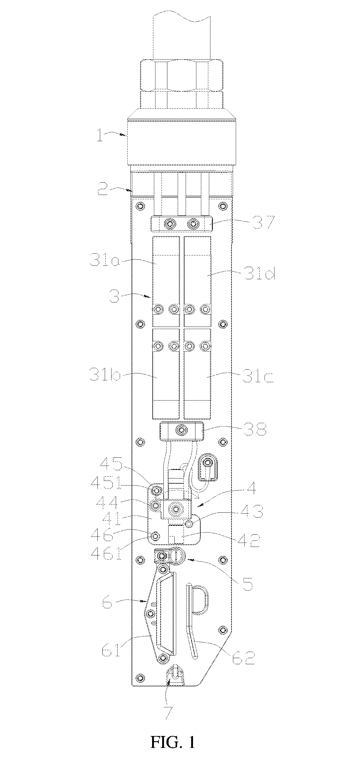
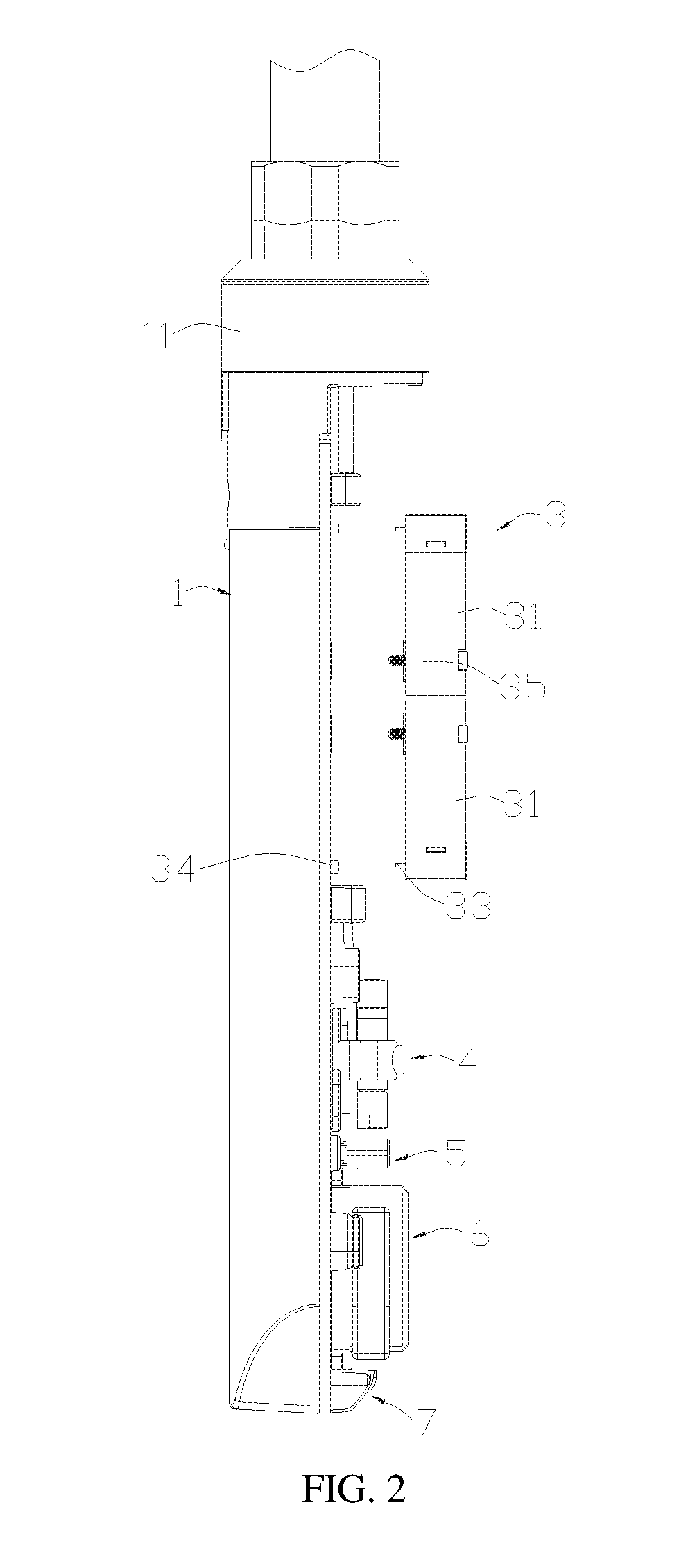
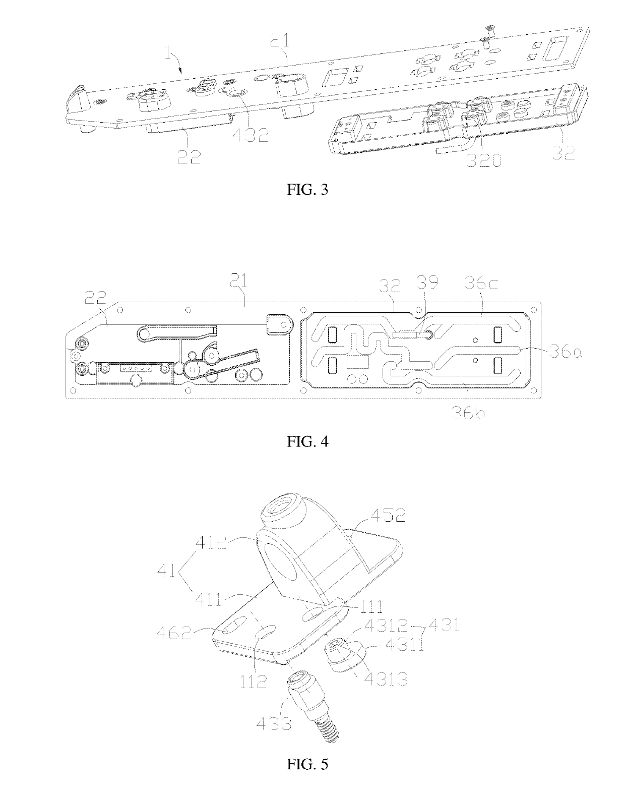
[0040]Referring to FIGS. 1-3, an inkjet head device for an inkjet printer in an embodiment of the present disclosure includes a base 1, a composite plate 2 and an inkjet head assembly. The inkjet head assembly is mounted on the composite plate 2 to form an integrated module, thereby the disassembly, the assembly and the maintenance of the inkjet head assembly are convenient. The base 1 is a tubular base having an open side extending axially. The composite plate 2 includes a fiberglass plate 21 and a plastic plate 22 integrally connected to the fiberglass plate 21. The fiberglass plate 21 is engaged with the open side of the base 1 along an axial direction of the base 1. The plastic plate 22 is located on a surface facing the base 1 of the fiberglass plate 21.

[0041]The fiberglass plate 21 and the pla...


PUM


Abstract

The present disclosure provides an inkjet head device for inkjet printers, which includes a tubular base, a composite plate and an inkjet head assembly mounted on the composite plate; the composite plate includes a fiberglass plate and a plastic plate integrally connected to the fiberglass plate, the fiberglass plate is engaged with the open side of the base along an axial direction of the base, the plastic plate is located on a surface facing the base of the fiberglass plate. According to the inkjet head device for inkjet printers of the disclosure, the base plate is a composite plate formed by integrally connecting the fiberglass plate and the plastic plate, where the inkjet head assembly is mounted to form an integrated module, thus the disassembly, the assembly, or the maintenance are convenient.

Description

CROSS REFERENCE TO RELATED APPLICATIONS[0001]The present application is a Continuation Application of PCT Application No. PCT / CN2018 / 084614 filed on Apr. 26, 2018, which claims the benefit of Chinese Patent Application Nos. 201820115794.X and 201820115823.2 filed on Jan. 23, 2018. All the above are hereby incorporated by reference.TECHNICAL FIELD[0002]The present disclosure relates to the technical field of inkjet printing, and more particularly, to an inkjet head device for inkjet printers.BACKGROUND[0003]Printing required patterns or marks on irregular surfaces is achieved by printers utilizing a non-contact automatic inkjet printing technology. The non-contact automatic inkjet printing technology is characterized in that an inkjet head device is applied in an electronic control mode to print required patterns or marks such as the production date, the batch number, the shelf life, etc., on irregular product packaging surfaces, which may be synchronously operated with the productio...

Claims


Application Information

Patent Timeline
IPC IPC(8): B41J2/14B41J2/05
CPCB41J2/14024B41J2/05B41J2/1433B41J2002/0055B41J2/02B41J2/175B41J2/09B41J2/17596
Inventor LIU, JINSONGCHEN, JINGBIAOFU, GUOZHENGHE, YUANDONGHE, KE
Owner LEAD TECH ZHUHAI ELECTRONICS CO LTD
Why Eureka
Eureka Blog
Learn More