Information bits for polar codes with mixed criteria
Active Publication Date: 2019-07-25
TELEFON AB LM ERICSSON (PUBL)
View PDF10 Cites 1 Cited by
Summary
Abstract
Description
Claims
Application Information
AI Technical Summary
This helps you quickly interpret patents by identifying the three key elements:
Problems solved by technology
Method used
Benefits of technology
Benefits of technology
The patent text discusses the challenge of placing known or partially known bits in a data set to achieve multiple performance criteria, such as minimizing block error rate and reducing decoding latency. The technical effect of the patent is to provide specific placements of these bits that can improve error performance and early termination benefits, simultaneously satisfying multiple performance criteria.
Problems solved by technology
The finite-length performance of polar codes under SC, however, is not competitive compared to other modern channel coding schemes such as low-density parity-check (LDPC) codes and Turbo codes.
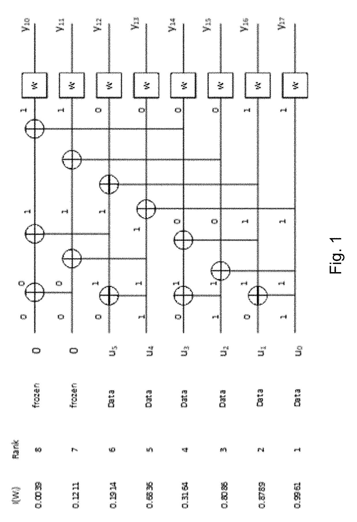
Some of the bit channels are nearly perfect (i.e., error free) while the rest of them are nearly useless (i.e., totally noisy).
Because typically only one of the many beams carrying the same system information can reach a particular receiver with good signal strength, the receiver does not know the location of the received beam in the overall radio frame structure.
In existing solutions, the known or partially known bits are placed in arbitrary positions, which does not enable the decoder to effectively use the known bit values during the decoding process to optimize given performance criteria.
However, to accomplish both goals, it is not clear how to place the known and partially known bits to achieve a good compromise.
However, with existing solutions it is unclear how multiple criteria may be satisfied with the placement of known or partially known bits.
Method used
Image
Click on the blue label to locate the original text in one second.
Reading with bidirectional positioning of images and text.
Examples
example 1a
[0081]Known bits are placed at the earliest decoding positions to achieve early termination benefits:
Indices for Placement beforePBCH Bit FieldsCRC InterleaverSS Block Time Index (3 bits);[0, 2, 3]
[0082]An example is illustrated in FIG. 6. FIG. 6 illustrates a set of known bits to be placed in the earliest decoding positions, according to a particular embodiment.
[0083]Known bits to be placed at the least reliable positions to achieve error performance enhancements after placing the above bits:
[0087]An example is illustrated in FIG. 8. FIG. 8 illustrates another set of known bits to be placed in the bit positions with lowest reliabilities, according to a particular embodiment.
example 1c
[0088]Known bits to be placed at the earliest decoding positions to achieve early termination benefits (an example is illustrated in FIG. 6):
Indices for Placement beforePBCH Bit FieldsCRC InterleaverSS Block Time Index (3 bits);[0 2 3]
[0089]Known bits to be placed at the least reliable positions to achieve error performance enhancements after placing the above bits:
[0090]An example is illustrated in FIG. 9. FIG. 9 illustrates another set of known bits to be placed in the bit positions with lowest reliabilities, according to a particular embodiment.
PUM
Abstract
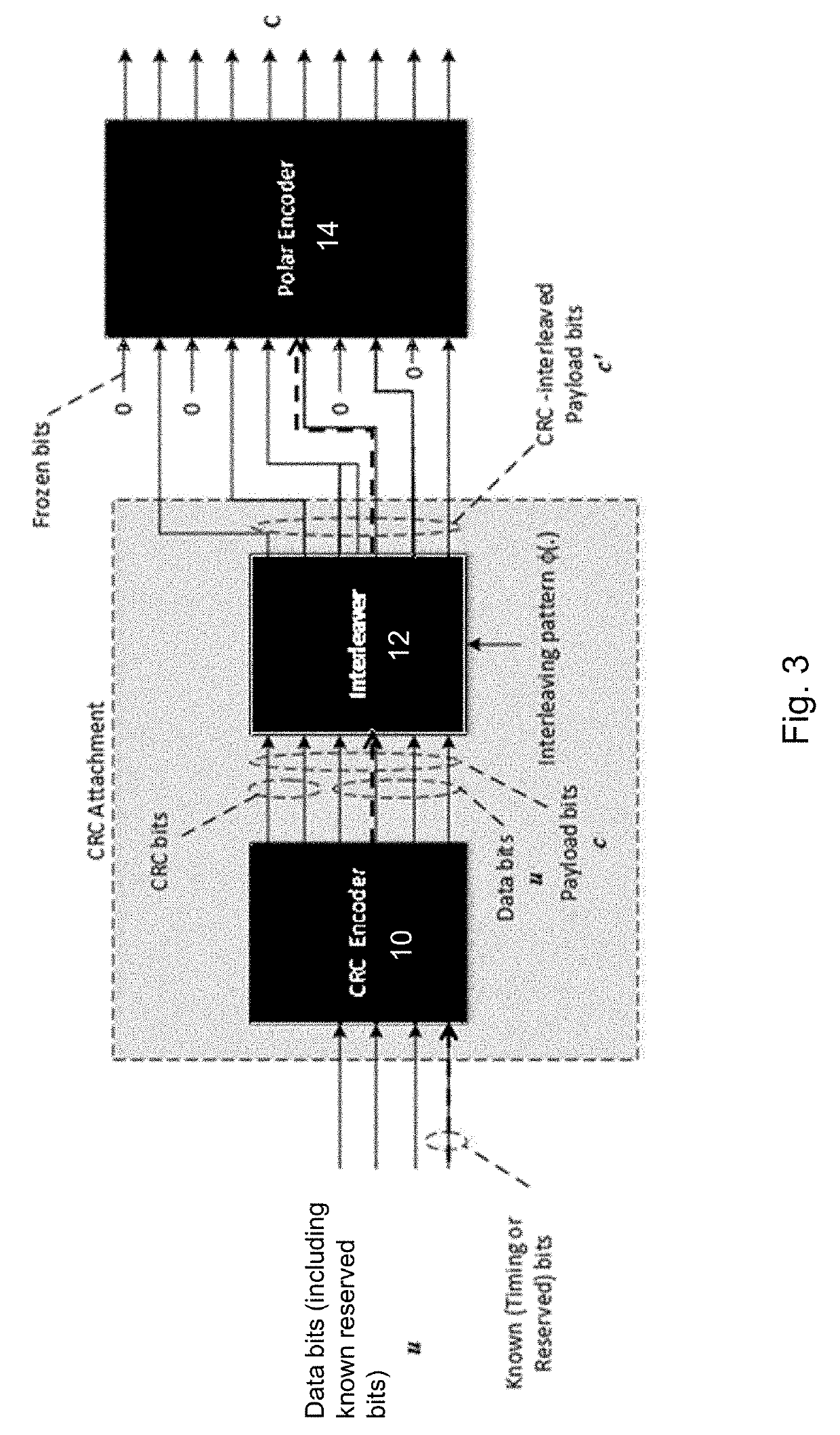
According to some embodiments, a method performed by a wireless device for polar encoding payload bits comprises: identifying payload bits of a data channel that have known values; placing a first subset of the known payload bits at input positions of a polar encoder that correspond to the earliest decoding bit positions of the polar encoder; placing a second subset of the known payload bits at input positions of the polar encoder that correspond to the least reliable decoding bit positions of the polar encoder after placement of the first subset of the known payload bits; and transmitting the polar encoded payload bits to a wirelessreceiver. The first subset of the known payload bits are placed in earliest decoding bit positions to improve early termination gain. The second subset of the known payload bits are placed in least reliable decoding bit positions to enhance error performance.
Description
[0001]This application is a continuation of International Application No. PCT / IB2018 / 059180, filed Nov. 21, 2018, which claims the benefit of U.S. Provisional Application No. 62 / 590,520, filed Nov. 24, 2017, the disclosure of which is fully incorporated herein by reference.TECHNICAL FIELD[0002]Particular embodiments are directed to wireless communications and, more particularly, to polar coding and selection of information bit placement based on mixed criteria.INTRODUCTION[0003]Generally, all terms used herein are to be interpreted according to their ordinary meaning in the relevant technical field, unless a different meaning is clearly given and / or is implied from the context in which it is used. All references to a / an / the element, apparatus, component, means, step, etc. are to be interpreted openly as referring to at least one instance of the element, apparatus, component, means, step, etc., unless explicitly stated otherwise.[0004]The steps of any methods disclosed herein do not ...
Claims
Application Information
Patent Timeline
Application Date:The date an application was filed.
Publication Date:The date a patent or application was officially published.
First Publication Date:The earliest publication date of a patent with the same application number.
Issue Date:Publication date of the patent grant document.
PCT Entry Date:The Entry date of PCT National Phase.
Estimated Expiry Date:The statutory expiry date of a patent right according to the Patent Law, and it is the longest term of protection that the patent right can achieve without the termination of the patent right due to other reasons(Term extension factor has been taken into account ).
Invalid Date:Actual expiry date is based on effective date or publication date of legal transaction data of invalid patent.

