Ribbon rewinding mechanism for providing stable ribbon tension in a printer

a rewinding mechanism and ribbon technology, applied in printing, inking apparatus, thin material processing, etc., can solve the problems of affecting the stability of the overall mechanism, the inability to completely rewind the carbon ribbon, and the need for rewinding the ribbon, etc., to achieve stable ribbon tension, low cost, and high operational stability

Active Publication Date: 2019-08-01
TSC AUTO TECH
View PDF4 Cites 0 Cited by
  • Summary
  • Abstract
  • Description
  • Claims
  • Application Information

AI Technical Summary

Benefits of technology

[0008]In response to the above-referenced technical inadequacies, the present disclosure provides a ribbon rewinding mechanism for providing stable ribbon tension in a printer, which serves as a low cost solution having high operational stability.

Problems solved by technology

However, the conventional torsion-spring-aided ribbon rewinding design for a label printer only allows the carbon ribbon to be rewound for a short distance.
In applications requiring printing of longer distances, the carbon ribbon cannot be rewound completely.
However, such a solution not only involves a more complicated overall mechanism and incurs higher costs, but is prone to cause the carbon ribbon to be too loose or too tight if there is an improper rotational speed design or a change in motor characteristics after being used for a long time.
A loose carbon ribbon may cause ribbon wrinkling during a printing process, and therefore affect printing quality; and a carbon ribbon that is too tight is prone to break.
As the technical solution of driving the ribbon supply shaft and the ribbon take-up shaft respectively by a DC motor to rewind a belt body not only incurs higher costs and difficulties in adjusting for ideal working conditions, but also has less-than-desired stability, there is still room for improvement in belt body rewinding techniques.

Method used


Image

  • Ribbon rewinding mechanism for providing stable ribbon tension in a printer
  • Ribbon rewinding mechanism for providing stable ribbon tension in a printer
  • Ribbon rewinding mechanism for providing stable ribbon tension in a printer

Examples


first embodiment

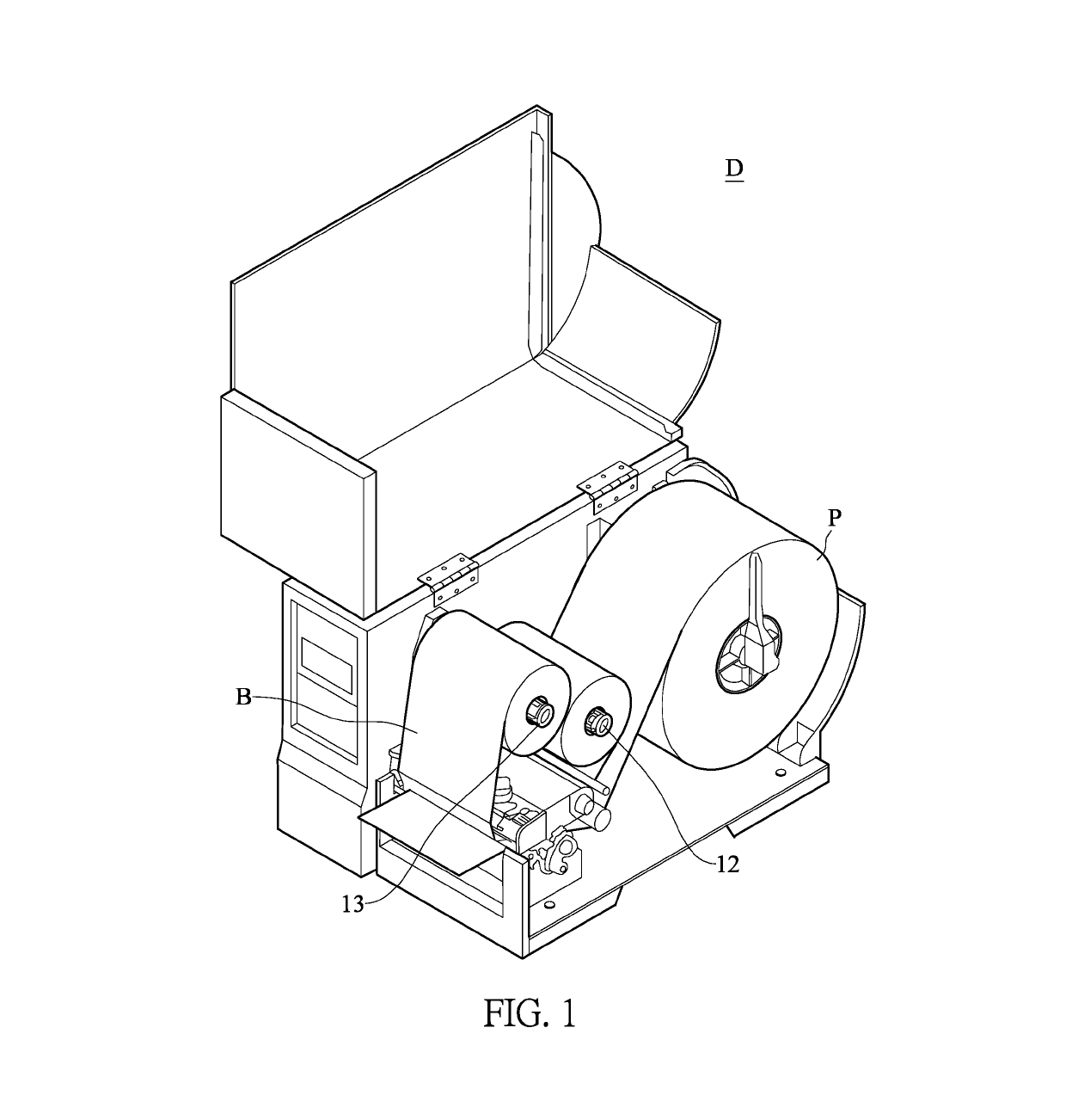
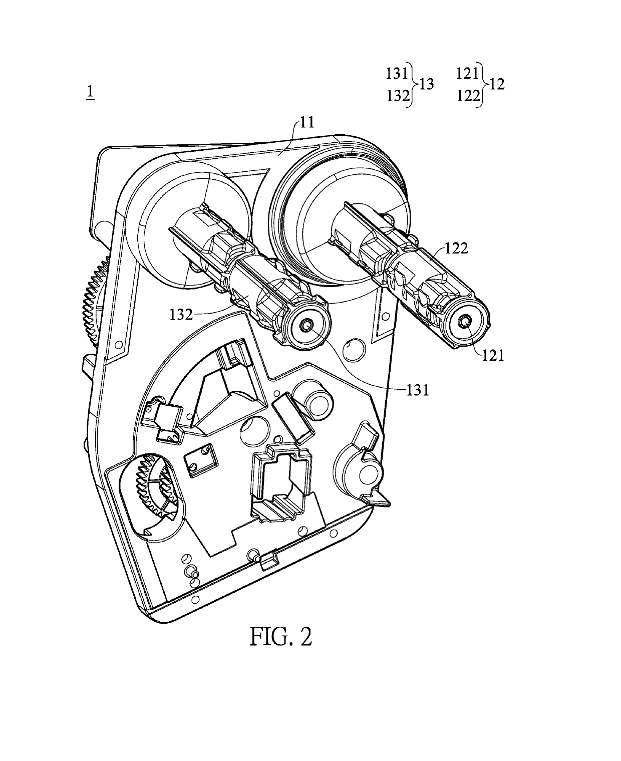
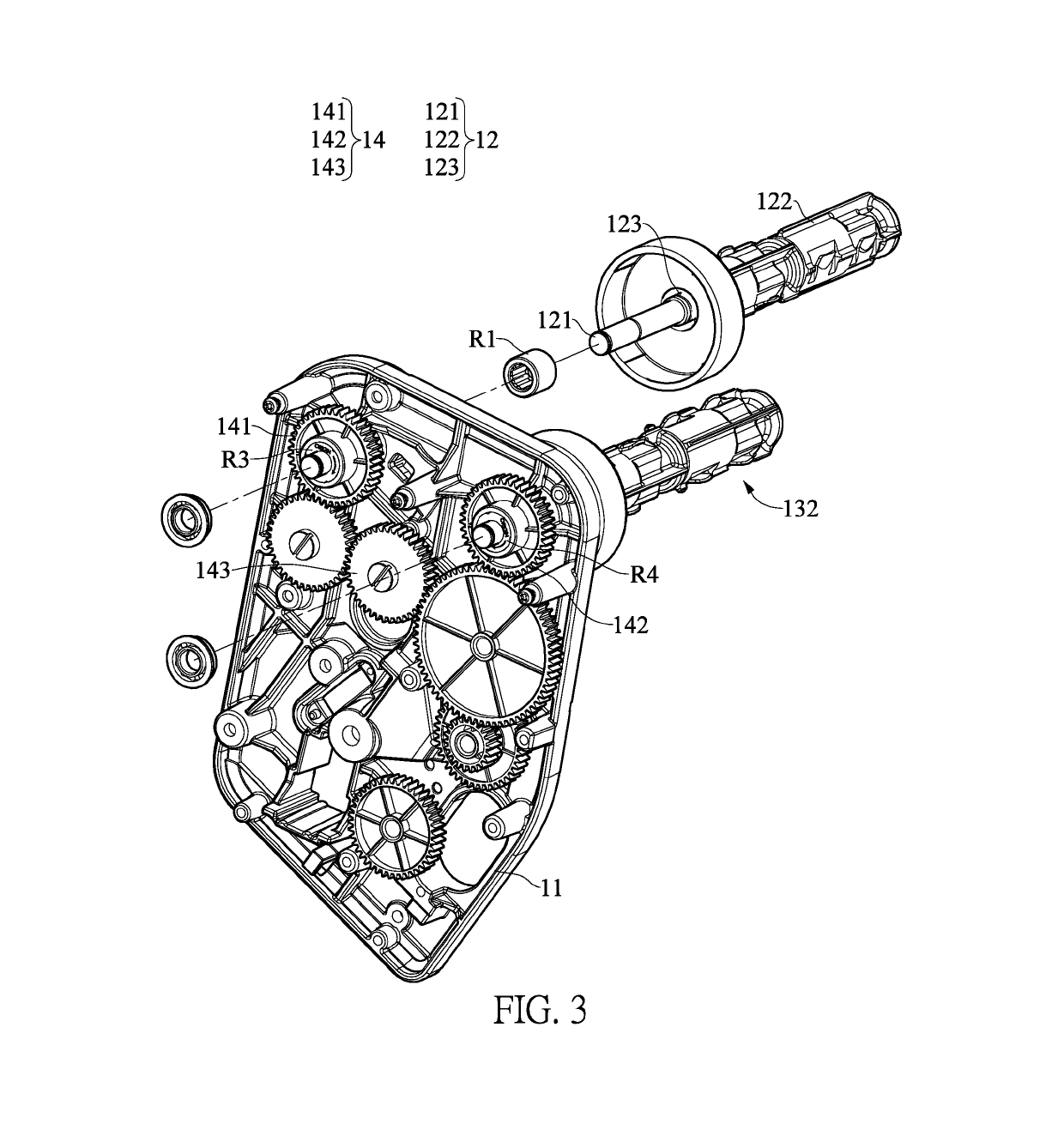
[0022]Reference is made to FIG. 1 and FIG. 2. FIG. 1 is a structural view of a printer D according to the first embodiment of the present disclosure. FIG. 2 is a perspective assembled view of a ribbon rewinding mechanism 1 for providing stable ribbon tension in a printer according to the first embodiment of the present disclosure. As can be seen from FIG. 1 and FIG. 2, the ribbon rewinding mechanism 1 for providing stable ribbon tension in the printer D according to the first embodiment of the present disclosure includes a base body 11, a supply shaft assembly 12, a take-up shaft assembly 13, a driving unit (not shown in the figures), and a transmission system 14 (as shown in FIG. 3). It should be noted in advance that descriptions relating to the terms “supply” and “take-up” in the present disclosure are mainly based on the roles of the ribbon rewinding mechanism 1 serving in a normal working state (namely, a printing state) of the printer D, in which the shaft assembly used to pro...

second embodiment

[0037]Referring again to FIG. 3, it is noted that while in the first embodiment of the present disclosure the transmission system 14 includes components such as a supply gear 141, a take-up gear 142 and a transmission gear set 143, in other embodiments, the transmission system 14 can include a supply pulley, a take-up pulley, a transmission belt, and the like. In the second embodiment, the supply pulley is connected to the third unidirectional transmission element R3, the take-up pulley is connected to the fourth unidirectional transmission element R4, and the supply pulley and the take-up pulley are mutually connected by the transmission belt. Such an arrangement can also achieve the purpose served by the transmission system 14 of the present disclosure, and therefore also falls within the scope covered by the transmission system 14 of the present disclosure. Similarly, other transmission methods sufficient to achieve the same or similar transmission effects are also within the sco...


PUM


Abstract

A ribbon rewinding mechanism for providing stable ribbon tension in a printer includes a base body, a supply shaft assembly, a take-up shaft assembly and a transmission system. Each of the supply shaft assembly and the take-up shaft assembly has an axis rod, an outer cover and an elastic member. The outer cover and the axis rod drive each other through the elastic member. The outer covers of the supply shaft assembly and the take-up shaft assembly are connectable to the two ends of a ribbon, respectively. The axis rods of the supply shaft assembly and the take-up shaft assembly are connected to the base body and the transmission system through unidirectional transmission elements, respectively, so that the ribbon can be stably and continuously rewound for a distance needed.

Description

CROSS-REFERENCE TO RELATED PATENT APPLICATION[0001]This application claims the benefit of priority to Taiwan Patent Application No. 107201399, filed on Jan. 29, 2018. The entire content of the above identified application is incorporated herein by reference.[0002]Some references, which may include patents, patent applications and various publications, may be cited and discussed in the description of this disclosure. The citation and / or discussion of such references is provided merely to clarify the description of the present disclosure and is not an admission that any such reference is “prior art” to the present disclosure described herein. All references cited and discussed in this specification are incorporated herein by reference in their entireties and to the same extent as if each reference was individually incorporated by reference.FIELD OF THE PRESENT DISCLOSURE[0003]The present disclosure relates to a ribbon rewinding mechanism for providing stable ribbon tension, and more p...

Claims


Application Information

Patent Timeline
Patent Type & Authority Applications(United States)
IPC IPC(8): B41J15/16B65H18/10B65H23/18
CPCB41J15/16B65H18/103B65H23/1806B41J33/40
Inventor CHEN, YU-ZHILU, ZHI-HAOYU, I-CHECHEN, YAN-ZHANG
Owner TSC AUTO TECH
Why Eureka
Try Eureka