Light Emitter

a technology of light emitters and light tubes, applied in the field of light emitters, can solve problems such as poor cooling efficiency, and achieve the effect of more flexibility

Active Publication Date: 2019-08-01
SEIKO EPSON CORP
View PDF37 Cites 0 Cited by
  • Summary
  • Abstract
  • Description
  • Claims
  • Application Information

AI Technical Summary

Benefits of technology

[0021]In the thus configured light emitter, the height of the light emitting device and the height of the sub-mount can be more flexibly set.

Problems solved by technology

Therefore, in the biological sensing apparatus described in JP-A-2016-111211, the heat is dissipated toward the interior of the product, where the sensor and other parts are present, resulting in poor cooling efficiency.

Method used


Image

  • Light Emitter
  • Light Emitter
  • Light Emitter

Examples


Embodiment Construction

[0040]A preferable embodiment of the invention will be described below in detail with reference to the drawings. It is not intended that the embodiment described below unduly limits the contents of the invention set forth in the appended claims. Further, all configurations described below are not necessarily essential configuration requirements of the invention.

1. Light Emitter

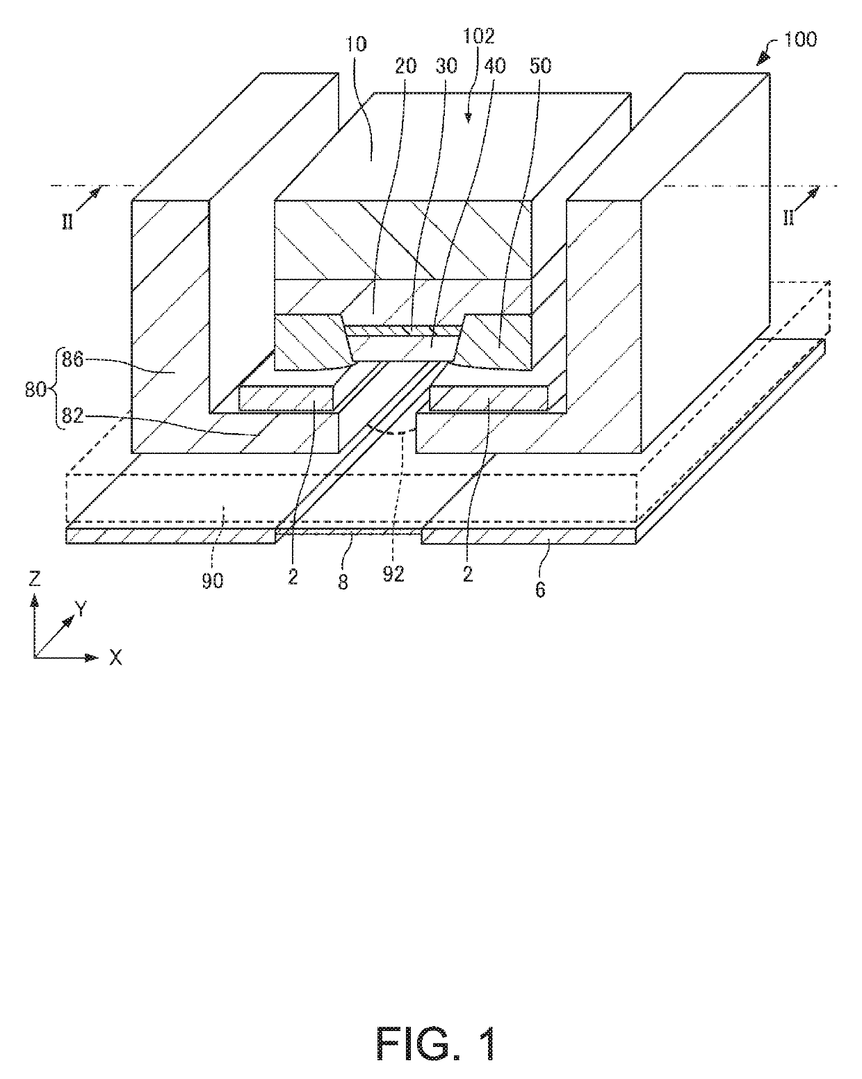
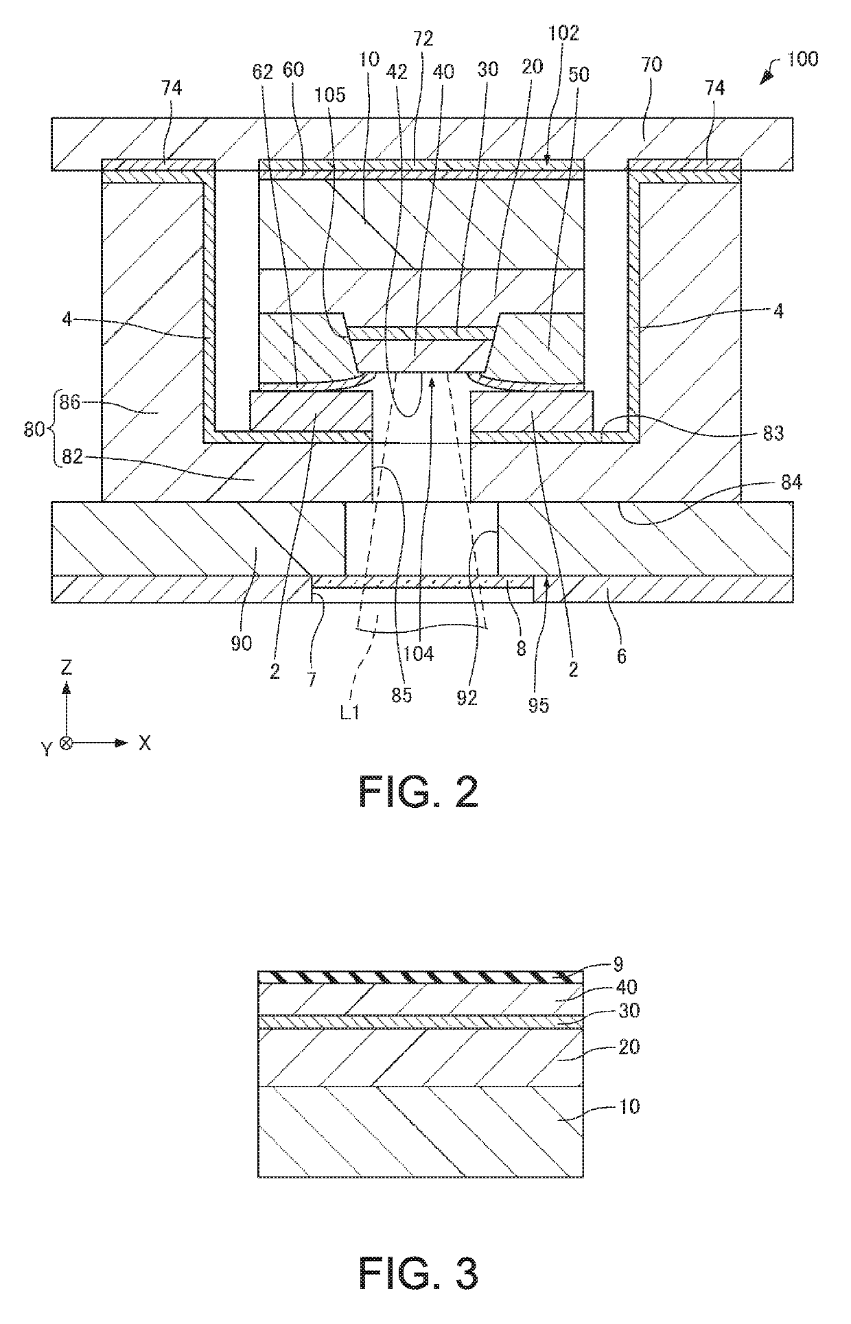
[0041]A light emitter according to the present embodiment will first be described with reference to the drawings. FIG. 1 is a cross-sectional perspective view diagrammatically showing a light emitter 100 according to the present embodiment. FIG. 2 is a cross-sectional view diagrammatically showing the light emitter 100 according to the present embodiment and taken along the line II-II in FIG. 1. In FIG. 1, wiring 4, electrodes 60 and 62, and a circuit substrate 70 are omitted for convenience. Further, in FIG. 1, a cooler 90 is drawn in a see-through manner. FIGS. 1 and 2 further show axes X, Y, and Z as three ...


PUM


Abstract

A light emitter includes a substrate, a first mirror layer provided on the substrate, a columnar section including an active layer provided on a side of the first mirror layer that is the side opposite the substrate and a second mirror layer provided on a side of the active layer that is the side opposite the first mirror layer, a semi-insulating member provided on the side surface of the columnar section and having thermal conductivity higher than the thermal conductivity of the first mirror layer and the thermal conductivity of the second mirror layer, and a sub-mount which has a first surface bonded to the semi-insulating member and through which light produced in the active layer passes, and a second surface of the sub-mount that is the surface opposite the first surface is oriented in the direction in which the light produced in the active layer exits.

Description

BACKGROUND1. Technical Field[0001]The present invention relates to a light emitter.2. Related Art[0002]In recent years, a wearable terminal worn by a human body, such as a wristband activity monitor or a smartwatch, has been widely used. For example, JP-A-2016-111211 describes a biological sensing apparatus including a light emitter that irradiates a human body with light and an image sensor that receives part of light scattered in the human body in the form of reflected light and acquiring biological information, such as a specific component in the blood.[0003]A light emitting device, such as a vertical cavity surface emitting laser (VCSEL) used as a light emitting device, is mounted on a mounting substrate. The light emitting device is formed by crystal growth of a first mirror layer, an active layer, and a second mirror layer on a semiconductor substrate. In general, in the case where the light emitting device is mounted on the mounting substrate, the substrate-side surface of th...

Claims


Application Information

Patent Timeline
Patent Type & Authority Applications(United States)
IPC IPC(8): H01S5/024F21V7/00F21V5/04H01L33/64
CPCH01S5/02415H01S5/02438F21V7/0091F21V5/04H01L33/64H01L33/20H01L33/486H01L33/645H01S5/183H01S5/02476H01S5/0234H01S5/02345H01S5/18347H01S5/18352
Inventor MOCHIZUKI, MASAMITSU
Owner SEIKO EPSON CORP
Why Eureka
Try Eureka