Polarization-sensitive pancake optics
a technology of polarization and pancakes, applied in the field of computer-based entertainment, can solve the problems of adding a counter balance, affecting the use of the head-mounted device, and affecting the use of the display devi
- Summary
- Abstract
- Description
- Claims
- Application Information
AI Technical Summary
Benefits of technology
Problems solved by technology
Method used
Image
Examples
first embodiment
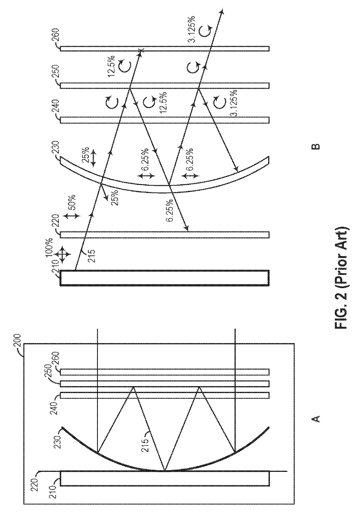
[0029]FIG. 4 illustrates a display device 400 with modified pancake optics, according to a As shown in panel A, the display device 400 includes a display 410 and an arrangement of optical elements including a linearly polarization-selective mirror element 420, a quarter-wave plate element 430, a 50 / 50 (half-silvered) flat beam splitter element 440, and a circular polarizer element 450. The display 410 is similar to the display 210 of the display device 200, discussed above, and will not be described in detail herein for conciseness. Although depicted as flat for illustrative purposes, in some embodiments the display 410 may have a compound curve shape, which counteracts Petzval field curvature and may produce a better image quality with less distortion.
[0030]The optical arrangement of the display device 400 differs from that of the display device 200, as the quarter-wave plate element 430 and the flat beam splitter element 440 are both achromatic, and the linear polarizer element 2...
second embodiment
[0036]FIG. 5 illustrates a display device 500 with modified pancake optics, according to a As shown in panel A, the display device 500 includes a display 510 and an arrangement of optical elements including a linearly polarization-selective mirror element 520, a quarter-wave plate element 530, and a circularly polarization-selective beam-splitter element 540. The display 510, the linearly polarization-selective mirror element 520, and the quarter-wave plate element 530 are similar to the display 410, linearly polarization-selective mirror element 420, and quarter-wave plate element 430, respectively, of the display device 400, discussed above, and will not be described in detail herein for conciseness. In particular, the linearly polarization-selective mirror element 520 and the quarter-wave plate element 530 may be achromatic, and the quarter-wave plate element 530 may further be AR-coated like the quarter-wave plate element 430. The optical arrangement of the display device 500 d...
third embodiment
[0040]FIG. 6 illustrates a display device 600 with modified pancake optics, according to a As shown, the display device 600 includes a display 610 and an arrangement of optical elements including a flat linearly polarization-selective mirror element 620, a quarter-wave plate element 630, a flat beam splitter element 640, a lens element 650, and a circular polarizer element 660. The display 610, the polarization-selective mirror element 620, the quarter-wave plate element 630, the flat beam splitter element 640, and the circular polarizer element 660 are similar to the display 410, the polarization-selective mirror element 420, the quarter-wave plate element 430, the flat beam splitter element 440, and the circular polarizer element 450, respectively, of the display device 400 discussed above, and will not be described in detail herein for conciseness. In particular, the polarization-selective mirror element 620, the quarter-wave plate element 630, the flat beam splitter element 640...
PUM
 Abstract
Description
Claims
Application Information
 - R&D
- Intellectual Property
- Life Sciences
- Materials
- Tech Scout
- Unparalleled Data Quality
- Higher Quality Content
- 60% Fewer Hallucinations
Browse by: Latest US Patents, China's latest patents, Technical Efficacy Thesaurus, Application Domain, Technology Topic, Popular Technical Reports.
© 2025 PatSnap. All rights reserved.Legal|Privacy policy|Modern Slavery Act Transparency Statement|Sitemap|About US| Contact US: help@patsnap.com


