
Spin torque layer in side gap for improved field and cross track field gradient

a technology of spin torque layer and side gap, which is applied in the field of computer system storage devices, can solve the problems of affecting the operation of the magnetic head, prone to leakage of magnetic flux from the main pole into the side shield, and conventional apparatus and methods that alter the side gap distan

Active Publication Date: 2019-08-08
WESTERN DIGITAL TECH INC
View PDF4 Cites 13 Cited by
  • Summary
  • Abstract
  • Description
  • Claims
  • Application Information

AI Technical Summary

Benefits of technology

The present patent describes various embodiments of a magnetic recording head. These embodiments have different materials and layers positioned around the main pole of the head for different purposes. The technical effect of this design is to improve the performance and efficiency of the magnetic recording head in writing and reading data on magnetic surfaces.

Problems solved by technology

Conventional apparatus and methods that alter the side gap distance from a main pole, however, are prone to leaks of magnetic flux from the main pole into the side shield.
Such leaks can adversely affect the operation of the magnetic head.

Method used


Image

  • Spin torque layer in side gap for improved field and cross track field gradient
  • Spin torque layer in side gap for improved field and cross track field gradient
  • Spin torque layer in side gap for improved field and cross track field gradient

Examples


Embodiment Construction

[0026]Some embodiments will now be described with reference to the figures. Like elements in the various figures will be referenced with like numbers for consistency. In the following description, numerous details are set forth to provide an understanding of various embodiments and / or features. It will be understood, however, by those skilled in the art that some embodiments may be practiced without many of these details and that numerous variations or modifications from the described embodiments are possible. As used herein, the terms “above” and “below”, “up” and “down”, “upper” and “lower”, “upwardly” and “downwardly”, and other like terms indicating relative positions above or below a given point or element are used in this description to more clearly describe certain embodiments.

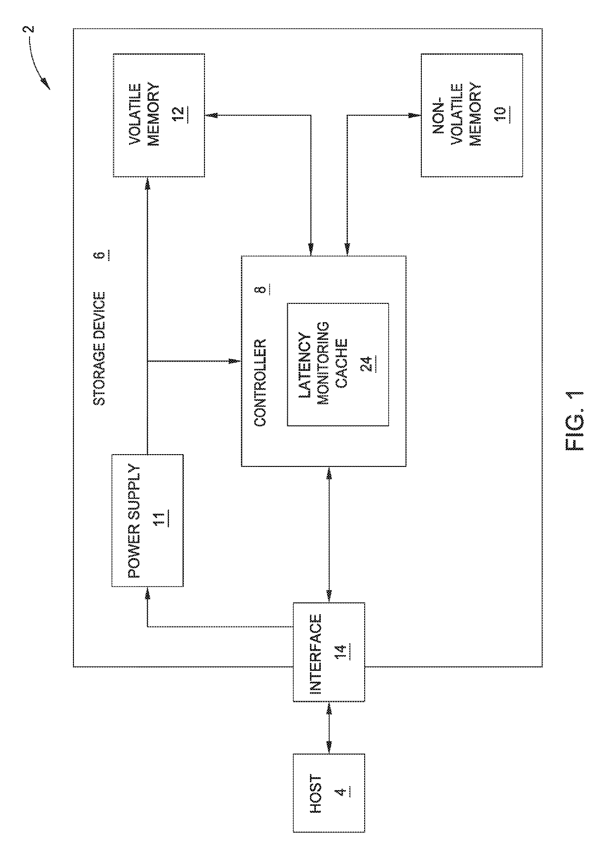
[0027]Aspects of the present disclosure relate to computer operations and computer storage. In the embodiments described, a data storage arrangement is connected to a host system. The function of the da...


PUM


Abstract

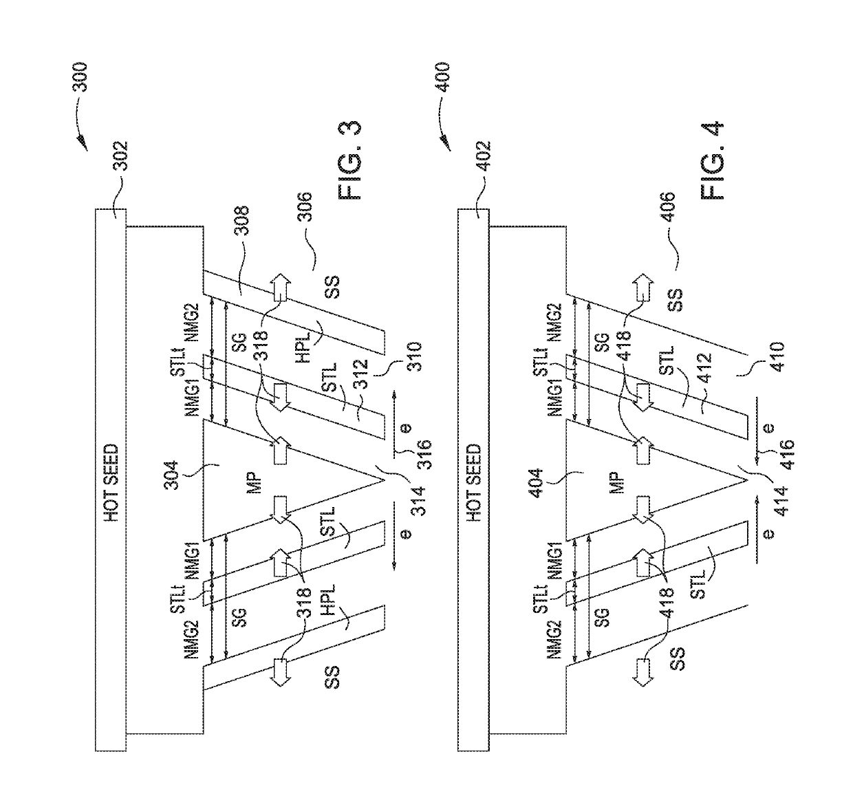
A magnetic recording head is disclosed having a main pole, a shield hot seed layer positioned at a first side of the main pole, a first material positioned at both a second side and a third side of the main pole, the first material connected to the main pole, a second material positioned adjacent to the first material on the second side and the third side of the main pole, the second material comprised of a spin torque layer, a third material positioned adjacent to the second material on the second side and the third side of the main pole, a fourth material positioned adjacent to the third material on the second side and the third side of the main pole and a side shield connected on an exterior side of the fourth material.

Description

CROSS-REFERENCE TO RELATED APPLICATIONS[0001]This application is a continuation of co-pending U.S. patent application Ser. No. 16 / 017,896, filed Jun. 25, 2018, which claims benefit of U.S. Provisional Application 62 / 570,030 dated Oct. 9, 2017. Each of the aforementioned related patent applications is herein incorporated by reference.BACKGROUND OF THE DISCLOSUREField of the Disclosure[0002]Aspects of the disclosure relate to storage devices for computer systems. More specifically, aspects of the disclosure relate to methods and apparatus to increase storage capacity per unit area of memory systems.Description of the Related Art[0003]Conventional perpendicular magnetic recording devices (PMR) are reaching fundamental limits regarding field and cross track field gradients. Magnetic recording and reproduction arrangements record and read information through a magnetization direction of a disk or other medium. Reading such magnetization on a disk with a head configured for such activitie...

Claims


Application Information

Patent Timeline
IPC IPC(8): G11B5/23G11B5/11
CPCG11B5/23G11B5/11G11B5/1278G11B5/235G11B5/3146G11B5/315G11B2005/0024
Inventor GONCHAROV, ALEXANDERASIF BASHIR, MUHAMMADOLSON, JAMES TERRENCEVAN DER HEIJDEN, PETRUS ANTONIUS
Owner WESTERN DIGITAL TECH INC
Learn More