Magnetoresistance effect element, magnetic head and magnetic recording and/or reproducing system

a technology of magnetic head and effect element, which is applied in the field of magnetic head and magnetic recording and/or reproducing system, can solve the problems of limiting the increase of the substantially difficult to achieve a high rate of change in mr exceeding 20%, and difficult to obtain a value exceeding 20%, etc., to achieve the effect of utilizing the scattering effect depending on spin

Inactive Publication Date: 2005-08-30
KK TOSHIBA
View PDF11 Cites 118 Cited by
  • Summary
  • Abstract
  • Description
  • Claims
  • Application Information

AI Technical Summary

Benefits of technology

[0032]It is therefore an object of the present invention to eliminate the aforementioned problems and to provide a practical magnetoresistance effect element which has an appropriate value of resistance, which can be sensitized and which has a small number of magnetic layers to be controlled, while effectively utilizing the scattering effect depending on spin, and a magnetic head and magnetic recording and / or reproducing system using the same.
[0034]According to a second aspect of the present invention, a magnetoresistance effect element comprises: a magnetoresistance effect film including a magnetization fixed layer having a ferromagnetic film in which the direction of magnetization is substantially fixed to one direction, a magnetization free layer having a ferromagnetic film in which the direction of magnetization varies in response to an external magnetic field, and an non-magnetic intermediate layer provided between the magnetization fixed layer and the magnetization free layer; a pair of electrodes which are electrically connected to the magnetoresistance effect film for applying a current in a direction perpendicular to the plane of the magnetoresistance effect film; and a resistant regulating layer for restricting the quantity of a sense current passing through the magnetoresistance effect film.

Problems solved by technology

On the other hand, it is difficult to obtain a value exceeding 20% as the rate of change in MR in conventional spin-valve films.
However, also in this construction, all of electrons do not always pass through the interface of magnetic material / non-magnetic material, so that there is a limit to the increase of the rate of change in MR.
For that reason, also in the above described CIP-SV film wherein the electron reflective layers are inserted, it is substantially difficult to realize a high rate of change in MR exceeding 20% and a practical amount of change in resistance of 5 to 30Ω.
However, this value of resistance is generally very small.
However, it can not be said that such a value of resistance is sufficiently a large value, so that it is required to further increase the number of the layers.
However, as described above, it is required to alternately stack many magnetic and non-magnetic layers in order to increase the value of resistance in the CPP-MR element, and it is technically very difficult to individually control the magnetization of such many magnetic layers.
Therefore, the Mst increases, so that it is difficult to improve the sensitivity to the signal magnetic flux.
For that reason, although it is expected that the CPP artificial lattice type film has a rate of change in MR exceeding 30%, it is difficult to sensitize the film in order to use the film as an MR sensor for a head, so that it is substantially impossible to use the film as the MR sensor.
Therefore, it is difficult to sensitize the film in order to use the film as an MR sensor for a head, so that it is substantially difficult to use the film.
However, at present, it is difficult to realize a spin-valve film which can be used at a high packing density exceeding 100 Gbit / inch2, which has an appropriate value of resistance and a large amount of change in MR and which is magnetically sensitive.

Method used


Image

  • Magnetoresistance effect element, magnetic head and magnetic recording and/or reproducing system
  • Magnetoresistance effect element, magnetic head and magnetic recording and/or reproducing system
  • Magnetoresistance effect element, magnetic head and magnetic recording and/or reproducing system

Examples


first embodiment

(First Embodiment)

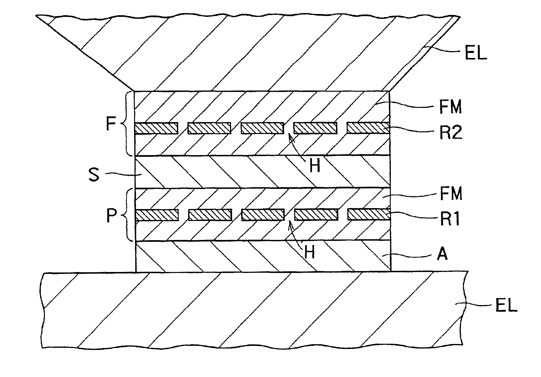
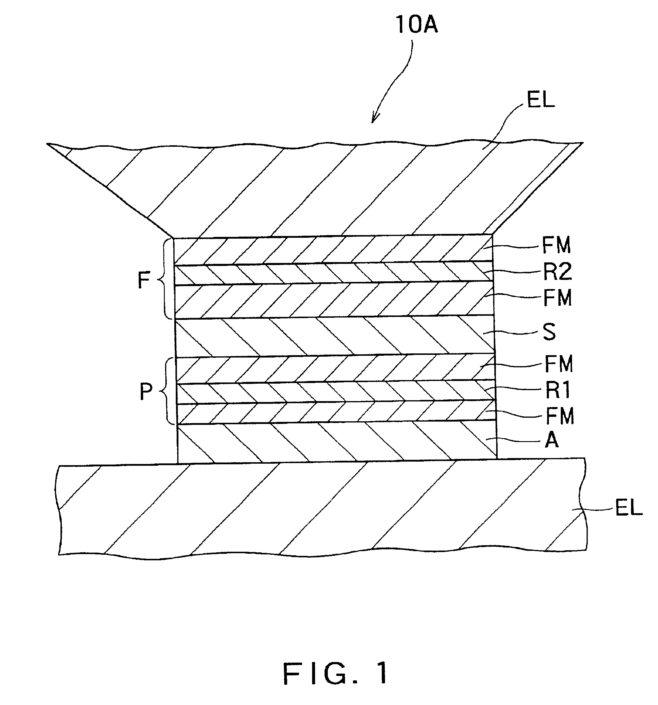
[0091]FIG. 1 is a conceptual drawing showing a cross-sectional structure of the first embodiment of a magnetoresistance effect element according to an aspect of the present invention. That is, the magnetoresistance effect element 10A according to the aspect of the present invention comprises an antiferromagnetic layer A, a first magnetic layer P, an non-magnetic intermediate layer S and a second magnetic layer F which are stacked on a predetermined substrate (not shown) in that order. In addition, a resistance regulating layer R1 is inserted into the first magnetic layer P, and a resistance regulating layer R2 is inserted into the second magnetic layer F. Furthermore, the antiferromagnetic layer A, the first magnetic layer P, the non-magnetic intermediate layer S and the second magnetic layer F constitute a magnetoresistance effect film.

[0092]Moreover, electrode layers EL are provided on the top and bottom faces of this stacked structure, respectively, and a sense ...

second embodiment

(Second Embodiment)

[0165]FIG. 18 is a conceptual drawing showing a cross-sectional structure of the second embodiment of a magnetoresistance effect element according to an aspect of the present invention. In this figure, the same reference numbers are given to the same elements as those described above referring to FIGS. 1 through 17, and the detailed descriptions thereof are omitted.

[0166]The magnetoresistance effect element in this embodiment also comprises an antiferromagnetic layer A, a first magnetic layer P, an non-magnetic intermediate layer S and a second magnetic layer F which are stacked on a predetermined substrate in that order, and a sense current I is caused to flow in a direction perpendicular to the plane of the film. Furthermore, the antiferromagnetic layer A, the first magnetic layer P, the non-magnetic intermediate layer S and the second magnetic layer F constitute a magnetoresistance effect film.

[0167]In addition, in this embodiment, a resistance regulating layer...

example 1

[0194]First, Example 1 of the present invention will be described below.

[0195]FIG. 21 is a conceptual drawing showing a cross-sectional construction of a first example of a magnetoresistance effect element according to the present invention. In the formation of this magnetoresistance effect element, a Cu bottom electrode EL1 having a thickness of 500 nm was first stacked on a thermally oxidized silicon (Si) substrate (not shown) by the sputtering method, and the Cu bottom electrode EL1 was formed so as to have a stripe shape having a width of 9 μm by the photolithography. Then, a CPP-SV 3 μm square was deposited thereon. The construction of the film was as follows.

[0196]Ta 5 nm (buffer layer B) / NiFe 2 nm (buffer layer B) / PtMn 15 nm (antiferromagnetic layer A) / CoFe 1 nm (pinned layer P1) / AlOx (resistance regulating layer R1) / CoFe 5 nm (pinned layer P2) / Cu 3 nm (non-magnetic intermediate layer S) / CoFe 5 nm (free layer F) / Cu 2 nm (non-magnetic layer NM1) / AlOx (resistance regulating lay...


PUM

PropertyMeasurementUnit
thicknessaaaaaaaaaa
distanceaaaaaaaaaa
resistanceaaaaaaaaaa

Abstract

There is provided a practical magnetoresistance effect element which has an appropriate value of resistance, which can be sensitized and which has a small number of magnetic layers to be controlled, and a magnetic head and magnetic recording and / or reproducing system using the same. In a magnetoresistance effect element wherein a sense current is caused to flow in a direction perpendicular to the plane of the film, a resistance regulating layer is provided in at least one of a pinned layer, a free layer and an non-magnetic intermediate layer. The resistance regulating layer contains, as a principal component, an oxide, a nitride, a fluoride, a carbide or a boride. The resistance regulating layer may be a continuous film or may have pin holes. Thus, it is possible to provide a practical magnetoresistance effect element which has an appropriate value of resistance, which can be sensitized and which has a small number of magnetic layers, while effectively utilizing the scattering effect depending on spin.

Description

CROSS REFERENCE TO RELATED APPLICATION[0001]This application is based upon and claims the benefit of priority from the prior Japanese Patent Applications No. 2000-321171, filed on Oct. 20, 2000; the entire contents of which are incorporated herein by reference.BACKGROUND OF THE INVENTION[0002]1. Field of the Invention[0003]The present invention relates generally to a magnetoresistance effect element, a magnetic head and a magnetic recording and / or reproducing system. More specifically, the invention relates to a magnetoresistance effect element using a spin-valve film wherein a sense current flows in a direction perpendicular to the plane of the thin film, a magnetic head including the magnetoresistance effect element, and a magnetic recording and / or reproducing system including the magnetoresistance effect element.[0004]2. Description of Related Art[0005]There is known a phenomenon that an electric resistance varies in response to an external magnetic field in a certain kind of fer...

Claims


Application Information

Patent Timeline
Patent Type & Authority Patents(United States)
IPC IPC(8): G11B5/39G11B5/31
CPCB82Y10/00B82Y25/00G01R33/093G11B5/39G11B5/3929H01F10/3272H01L43/08H01F10/3259G11B5/3903G11B5/3133G11B5/3143Y10T428/1114G11B2005/3996H10N50/10
Inventor KAMIGUCHI, YUUZOYUASA, HIROMINAGATA, TOMOHIKOYODA, HIROAKIKOUI, KATSUHIKOYOSHIKAWA, MASATOSHIIWASAKI, HITOSHISAHASHI, MASASHITAKAGISHI, MASAYUKI
Owner KK TOSHIBA
Why Eureka
Try Eureka