User terminal, rsu, method and program
a user terminal and user terminal technology, applied in the field of user terminals, can solve the problems of insufficient battery capacity of smart phones or the like considered as communication devices carried by pedestrians in many cases, and achieve the effect of reducing power consumption of communication devices carried by pedestrians
- Summary
- Abstract
- Description
- Claims
- Application Information
AI Technical Summary
Benefits of technology
Problems solved by technology
Method used
Image
Examples
first embodiment
3. FIRST EMBODIMENT
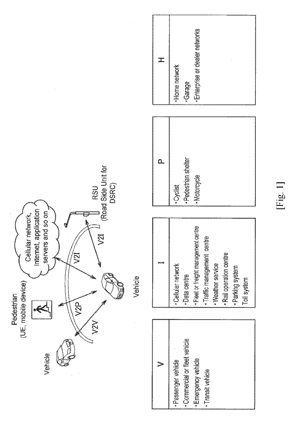
[0100]The present embodiment reduces power consumption by activating or deactivating the communication function of the UE 10 depending on position.
[0101]The UE 10 activates or deactivates the communication function by the wireless communication unit 120 on the basis of information acquired depending on position. For example, the UE 10 activates the communication function at a position at which a possibility of crash with the moving object 22 is high (e.g., the vicinity of a road or the like) and deactivates the communication function at a position at which the possibility is low (e.g., inside of a building). Accordingly, a communication function activation period may be minimized and thus power consumption may be reduced.
[0102]Particularly, the activated or deactivated communication function is the V2P communication function in the present embodiment. Of course, the V2P communication function corresponding to an activation or deactivation target includes the funct...
second embodiment
4. SECOND EMBODIMENT
[0184]The present embodiment further decreases power consumption by controlling reception timing or transmission timing in a state in which the communication function of the UE 10 has been activated.
[0185]Specifically, the UE 10 performs intermittent communication with the UE 20 or the RSU 50. The transmitting side performs intermittent transmission using a discontinuous transmission (DTX) scheme. On the other hand, the receiving side performs intermittent reception using a discontinuous reception (DRX) scheme. Communication opportunities of the UE 10 decrease in both a case in which the UE 10 is the transmitting side and a case in which the UE 10 is the receiving side, and thus power consumption may be decreased.
[0186]Hereinafter, a case in which the UE 10 performs DRX as a receiving side will be described first and then a case in which the UE 10 performs DTX as a transmitting side will be described. In the following description, a target of intermittent communi...
application examples
5. APPLICATION EXAMPLES
[0257]The technology of the present disclosure is applicable to various products. For example, the eNB 30 may be realized as any type of evolved Node B (eNB) such as a macro eNB, and a small eNB. A small eNB may be an eNB that covers a cell smaller than a macro cell, such as a pico eNB, micro eNB, or home (femto) eNB. Instead, the eNB may be realized as any other types of base stations such as a NodeB and a base transceiver station (BTS). The eNB may include a main body (that is also referred to as a base station device) configured to control wireless communication, and one or more remote radio heads (RRH) disposed in a different place from the main body. Additionally, various types of terminals to be discussed later may also operate as the eNB by temporarily or semi-permanently executing a base station function. Furthermore, at least part of components of the eNB 30 may be realized in a base station device or a module for the base station device.
[0258]For exa...
PUM
 Abstract
Description
Claims
Application Information
 - R&D
- Intellectual Property
- Life Sciences
- Materials
- Tech Scout
- Unparalleled Data Quality
- Higher Quality Content
- 60% Fewer Hallucinations
Browse by: Latest US Patents, China's latest patents, Technical Efficacy Thesaurus, Application Domain, Technology Topic, Popular Technical Reports.
© 2025 PatSnap. All rights reserved.Legal|Privacy policy|Modern Slavery Act Transparency Statement|Sitemap|About US| Contact US: help@patsnap.com


