Control system for a surveillance system, surveillance system and method of controlling a surveillance system

a control system and surveillance system technology, applied in the direction of television systems, instruments, image enhancement, etc., can solve the problem of not always being able to provide good image quality, and achieve the effect of improving the image quality of images and increasing the usefulness of captured images for users

Active Publication Date: 2019-08-08
SIGNIFY HLDG BV
View PDF3 Cites 3 Cited by
  • Summary
  • Abstract
  • Description
  • Claims
  • Application Information

AI Technical Summary

Benefits of technology

[0009]Hence, the image processor can analyse the image data received from the surveillance imaging device (e.g. including a video camera or the like) to determine the image quality of the images (e.g. those displayed in a control room). This information can be used by the lighting controller to control the lighting apparatuses so as to improve the image quality of the images. It will be appreciated that changing the lighting conditions for an area may cause the surveillance imaging device (e.g. a camera) to change its own capturing parameters (e.g. which may be automatically controlled via an algorithm). Hence, the lighting controller may control the lighting apparatuses so as to change the parameters of the surveillance imaging device (e.g. a camera).
[0010]The image quality parameter may comprise at least one of: a brightness value; a contrast value; a color balance value; and a shadow-contrast point value, a sharpness value, a noise value, a dynamic range value, a tone reproduction value, a colour accuracy value, a distortion value, an exposure accuracy value, a value indicative of lens flare. More generally, the image quality parameter may be any parameter of the image that can be determined by the image processor, an improvement of which can increase the usefulness of the captured images to a user.

Problems solved by technology

However, it is not always possible to provide good image quality.

Method used


Image

  • Control system for a surveillance system, surveillance system and method of controlling a surveillance system
  • Control system for a surveillance system, surveillance system and method of controlling a surveillance system
  • Control system for a surveillance system, surveillance system and method of controlling a surveillance system

Examples


Embodiment Construction

[0037]In the detailed description, the invention is described in relation to the monitoring of an outdoor areas illuminated with at least one outdoor lighting apparatus or system. However, the invention is not limited to outdoor applications and may also be used for surveillance of indoor areas.

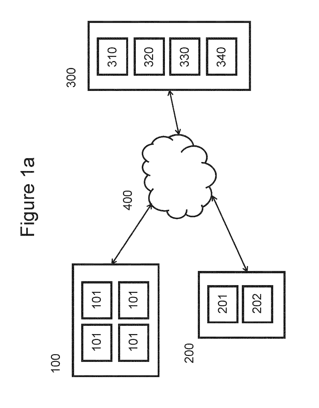
[0038]FIG. 1a shows a surveillance system according to a first embodiment of the invention.

[0039]The surveillance system comprises an outdoor lighting system 100, a surveillance imaging device 200 and a control system 300.

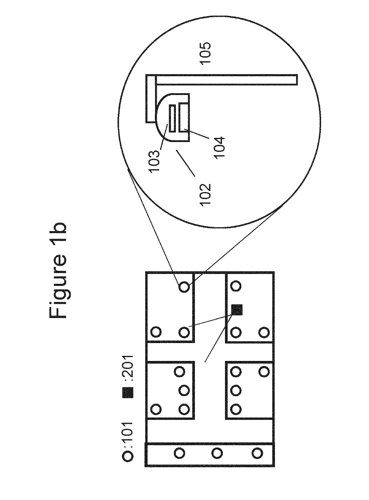
[0040]The outdoor lighting system 100 comprises a plurality of outdoor lighting apparatuses 101. Four outdoor lighting apparatuses 101 are shown in FIG. 1a, but this is purely as an example. FIG. 1b shows a plan view of an example street scene in which there are many outdoor lighting apparatuses 101. FIG. 1b also shows a schematic enlargement of one outdoor lighting apparatuses 101. As shown in more detail in FIG. 1b, an outdoor lighting apparatus 101 comprises a lighting un...


PUM


Abstract

A surveillance system is presented that aims to improve image quality. The surveillance system comprises a plurality of lighting apparatuses comprising one or more lights; a surveillance imaging device arranged to capture image data of a monitored area illuminated by one or more of the lighting apparatuses; an image processor arranged to receive the image data from the surveillance imaging device, wherein the image data comprises a plurality of frames, and the image processor is arranged to analyse each frame of the image data to obtain an image quality parameter for each frame; and a controller arranged to determine a difference between a value of the image quality parameter for a current frame and a reference value of the image quality parameter, wherein if said difference is greater than a threshold value. The controller is arranged to repeat a process of: 1) controlling a lighting parameter of at least one of the plurality of lighting apparatuses so as to change illumination of the monitored area; and 2) determining a new difference between a value of the image quality parameter for a new current frame and the reference value of the image quality parameter; until said new difference is less than or equal to a threshold value.

Description

FIELD OF THE INVENTION[0001]The invention relates to a control system for a surveillance system, a surveillance system and a method of controlling a surveillance system.BACKGROUND OF THE INVENTION[0002]It is common for surveillance systems to be used to monitor areas. Such systems typically use a camera or a set of cameras, the outputs of which are displayed at a control room. Often one operator needs to observe many displays with multiple live camera streams. For efficient video surveillance good image quality is crucial. However, it is not always possible to provide good image quality.[0003]It is an object of the invention to provide a surveillance system and method of controlling a surveillance system that overcomes problems associated with conventional devices.[0004]US 2008 / 180553 A1 discloses a video imager used to measure the natural and / or artificial light levels in a space. These lighting estimates may be passed to a controller via a communication network. The controller may...

Claims


Application Information

Patent Timeline
Patent Type & Authority Applications(United States)
IPC IPC(8): H05B37/02G08B13/196G06T7/00H04N5/235H04N7/18
CPCH05B37/0227H05B37/0218G08B13/196G06T7/0002H04N5/2354H04N7/183G06T2207/30168G06T2207/30232G06T2207/10024G06T2207/20104G08B13/194Y02B20/40H05B47/125H04N23/74H05B47/11
Inventor SINITSYN, ALEXANDRE GEORGIEVICHBUDDEMEIJER-LOCK, ANNEMARIE PAULIENVERHOEVEN, TOMDE VRIES, JUDITH HENDRIKA MARIA
Owner SIGNIFY HLDG BV
Why Eureka
Try Eureka