Method and apparatus for modulating x-ray tube current in computed tomography

a computed tomography and tube current technology, applied in the field of diagnostic imaging, can solve the problems of image artifacts, increase patient dose, and image steaking, and achieve the effects of sufficient x-ray tube current, avoiding streaking artifacts, and reducing patient dos

Active Publication Date: 2019-08-15
MINFOUND MEDICAL SYST CO LTD
View PDF0 Cites 1 Cited by
  • Summary
  • Abstract
  • Description
  • Claims
  • Application Information

AI Technical Summary

Benefits of technology

[0009]Thus, there is a need to reduce patient dose while maintaining sufficient x-ray tube current to avoid streaking artifacts.

Problems solved by technology

X-rays passing through the patient can cause x-ray scatter to occur, which can cause image artifacts.
Typically, higher tube current improves image quality, but likewise increases patient dose.
To reduce dose, x-ray tube current may be reduced, but insufficient x-ray tube current levels can result in steaking artifacts in the image.
However, such a dose often includes excessive x-ray flux during portions of the scan when patient attenuation is low (and thus the excess flux is unnecessary).
On the other hand, if the fixed level is too low, then noise artifacts may appear in the image where the beam is highly attenuated.
However, such an arrangement can still result in excess x-ray dose at rotational gantry angles where there is small attenuation.
However, this system may include excessive dose because attenuation characteristics of, for instance, a lung region are much smaller than a shoulder region.
Further, such known systems may include two scout scans such that sufficient information related to a scan may be obtained prior to actual imaging—resulting in excess dose due to the two scout scans.

Method used


Image

  • Method and apparatus for modulating x-ray tube current in computed tomography
  • Method and apparatus for modulating x-ray tube current in computed tomography
  • Method and apparatus for modulating x-ray tube current in computed tomography

Examples


Embodiment Construction

[0030]The operating environment of disclosed examples is described with respect to a multislice computed tomography (CT) system. Examples are described with respect to a “third generation” CT scanner, however it is contemplated that the disclosed examples are applicable to other imaging systems as well, and for CT systems having more or less than the illustrated sixty-four-slice system.

[0031]The present disclosure includes a method to substitute current reference channels used for projection data normalization by a factor based on a feedback current (mA) generated from a high voltage generator.

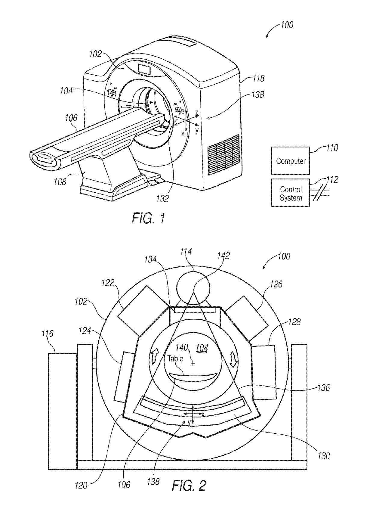
[0032]Referring to FIGS. 1 and 2, a computed tomography (CT) system 100 includes a gantry 102 having an opening 104. A patient table 106 is positioned on a support structure 108, and patient table 106 is axially controllable such that a patient (not shown) positioned on table 106 may be positioned within opening 104. A computer system 110 provides operator instructions and other control instru...


PUM


Abstract

A computed tomography (CT) system includes a rotatable gantry having an opening to receive an object to be scanned, a high-voltage generator, an x-ray tube positioned on the gantry to generate x-rays through the opening, a pixelated detector positioned on the gantry to receive the x-rays, and a computer. The computer is programmed to obtain a scout image of the object, calculate an equivalent diameter of a water cylinder based on the scout image over a length of the scout image, calculate a major axis and a minor axis for an equivalent ellipse over the length, calculate, based on a noise index and based on the equivalent diameter as the function of the length, an mA modulation as a function of the length, and obtain image data of the object by modulating an mA applied to the x-ray tube based on the calculated mA modulation.

Description

TECHNICAL FIELD[0001]This disclosure relates generally to diagnostic imaging and, more particularly, to a method and apparatus for reducing dose in a computed tomography (CT) system.BACKGROUND[0002]Typically, in computed tomography (CT) imaging systems, a rotatable gantry includes an x-ray tube, detector, data acquisition system (DAS), and other components that rotate about a patient that is positioned at the approximate rotational center of the gantry. X-rays emit from the x-ray tube, are attenuated by the patient, and are received at the detector. The detector typically includes a photodiode-scintillator array of pixelated elements that convert the attenuated x-rays into photons within the scintillator, and then to electrical signals within the photodiode. The electrical signals are digitized and then received within the DAS, processed, and the processed signals are transmitted via a slipring (from the rotational side to the stationary side) to a computer or data processor for ima...

Claims


Application Information

Patent Timeline
Patent Type & Authority Applications(United States)
IPC IPC(8): A61B6/00A61B6/03
CPCA61B6/544A61B6/035A61B6/583A61B6/545A61B6/40A61B6/4233A61B6/488A61B6/032A61B6/405
Inventor MIAO, CHUANGIKHLEF, ABDELAZIZ
Owner MINFOUND MEDICAL SYST CO LTD
Why Eureka
Try Eureka