Protective lighting method

a protective lighting and light technology, applied in the field of refractive therapy, can solve the problems of epidemic proportion, increase in incidence, and commercial success of hybrid lenses of this configuration

Pending Publication Date: 2019-08-15
MYOLITE
View PDF7 Cites 24 Cited by
  • Summary
  • Abstract
  • Description
  • Claims
  • Application Information

AI Technical Summary

Problems solved by technology

Hybrid lenses of this configuration enjoy commercial success with limitations due to the separation of the two materials at their radial junction, lens flexure and tear stagnation due to a circumferential sealing of the lens against the underlying eye.
The increase in incidence and resultant prevalence of myopia in the developed world and most particularly in Asia presents a problem of epidemic proportion.
The changes in life-style, living conditions and activity preferences often prevent the ability to engage in outdoor activities.
Although Neitz teaches the importance of wavelength modulation, the intervention is limited to filters of red light.
Such filters fail to modulate brightness above an ambient level.
They also fail to add the component of near visible ultraviolet light.
While the Correlated Color Temperature may fall within a level found in the range of daylight, the spectral power distribution most often has spikes and fails to represent outdoor daylight.

Method used


Image

  • Protective lighting method
  • Protective lighting method
  • Protective lighting method

Examples


Embodiment Construction

[0034]In the following paragraphs, the present invention will be described in detail by way of example with reference to the attached drawings. Throughout this description, the preferred embodiment and examples shown should be considered as exemplars, rather than as limitations on the present invention. As used herein, the “present invention” refers to any one of the embodiments of the invention described herein, and any equivalents. Furthermore, reference to various feature(s) of the “present invention” throughout this document does not mean that all claimed embodiments or methods must include the referenced feature(s).

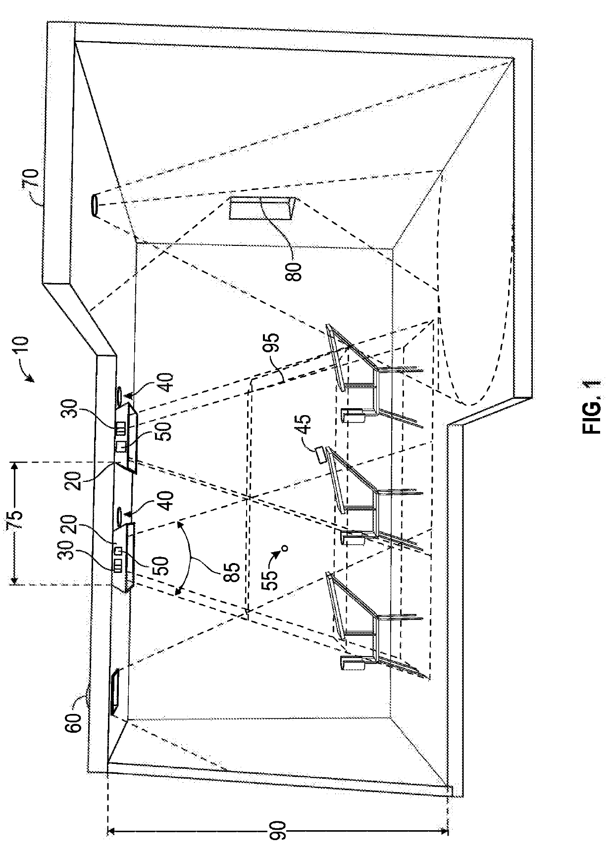
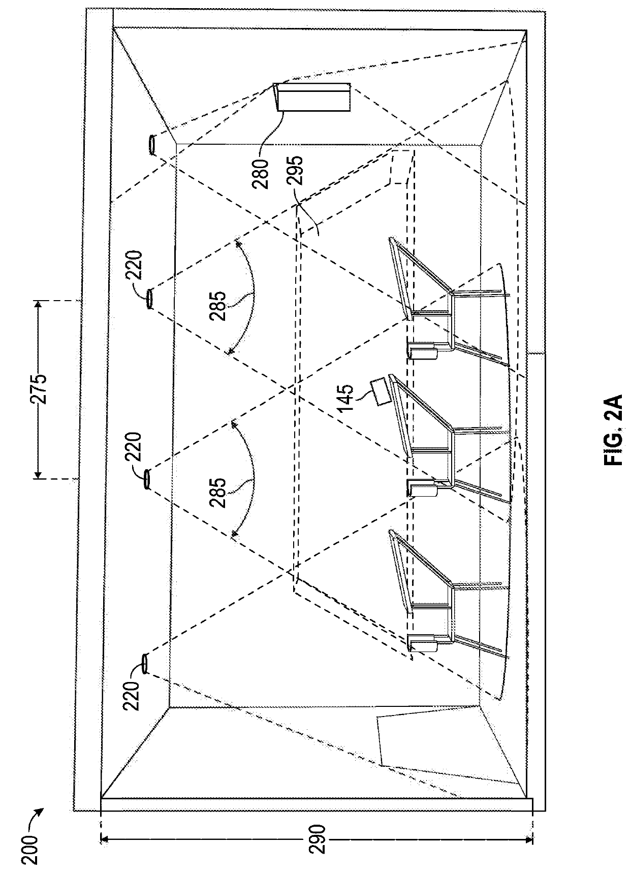
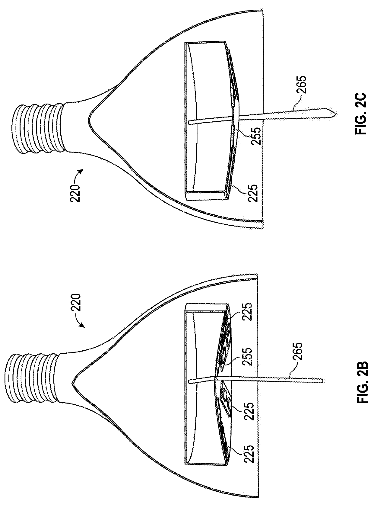
[0035]Embodiments of the invention provide an electromagnetic radiation system disposed on or within a space intended for occupants (e.g., humans) and including at least one electromagnetic radiation source that is directed toward the retina or passes through the eye off of the visual axis. By way of non-limiting example, the electromagnetic radiation source may comp...


PUM


Abstract

The present application is directed to a method for the regulation of the development of ocular refractive errors, comprising: controlling at least one light source using a processor, the at least one light source emitting an electromagnetic radiation variable with respect to one or more of a direction, an illuminance, a retinal area, an amplitude, a wavelength, and a spectral output; and regulating the at least one light source and producing a spectral power distribution at a plane of an eye.

Description

REFERENCE TO RELATED APPLICATIONS[0001]This application is a continuation of U.S. patent application Ser. No. 14 / 033,335, filed Sep. 20, 2013, which claims priority to U.S. Provisional Application No. 61 / 703,424, filed on Sep. 20, 2012, the contents of which are incorporated herein by reference in their entireties.FIELD OF THE INVENTION[0002]The present invention relates generally to refractive therapy, and more particularly, to lighting systems for the regulation of the development of refractive error.BACKGROUND OF THE INVENTION[0003]Refractive correction can be achieved through use of spectacle lenses, contact lenses, corneal refractive surgery and intraocular lens implantation. Contact lenses have evolved from non-gas-permeable rigid lenses which contact the sclera and vault the cornea to corneal contact lenses made of gas permeable products, and then to corneal-scleral contact lenses made of hydrogel materials. Hybrid lenses were created to provide the improved optics of rigid l...

Claims


Application Information

Patent Timeline
Patent Type & Authority Applications(United States)
IPC IPC(8): A61N5/06F21S4/20F21K9/23F21S8/04F21V19/02F21K9/65H05B33/08H05B44/00
CPCA61N5/0613F21S4/20F21K9/23F21S8/04F21V19/02F21K9/65H05B33/086A61N2005/0667F21Y2115/10Y02B20/341H05B45/20Y02B20/30A61N2005/0628A61N2005/0635
Inventor LEGERTON, JEROME A.CARLIN, STEVEN W.
Owner MYOLITE
Why Eureka
Try Eureka