Fuel cell system and method of controlling fuel cell system

a fuel cell and fuel cell technology, applied in the direction of fuel cells, motive system fuel cells, reactant parameter control, etc., can solve the problems of difficult to accurately control and the actual operating point of the turbo compressor may unintentionally enter the surging region, so as to suppress the occurrence of turbo surging

Active Publication Date: 2019-08-22
TOYOTA JIDOSHA KK
View PDF0 Cites 4 Cited by
  • Summary
  • Abstract
  • Description
  • Claims
  • Application Information

AI Technical Summary

Benefits of technology

[0012]The disclosure can also be realized in various aspects other than the fuel cell system. For example, the disclosure can be realize

Problems solved by technology

In this region, it is difficult to accurately control the actual operating point of the turbo compressor.
Therefore, even when the target opera

Method used


Image

  • Fuel cell system and method of controlling fuel cell system
  • Fuel cell system and method of controlling fuel cell system
  • Fuel cell system and method of controlling fuel cell system

Examples


first embodiment

A. First Embodiment

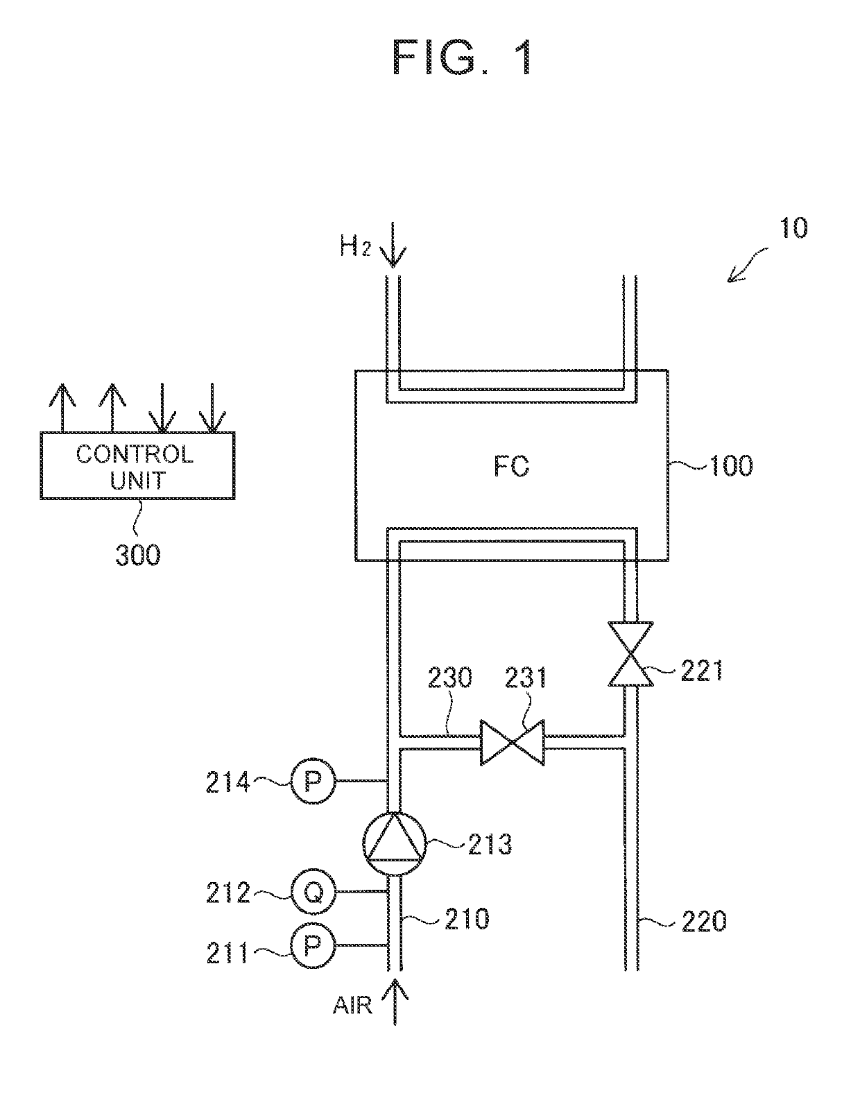
[0025]FIG. 1 is an illustrative view showing the overall configuration of a fuel cell system 10 according to the first embodiment. The fuel cell system 10 according to the present embodiment is mounted in, for example, a fuel-cell-powered vehicle, and is used as an electric power generation device for driving a motor for driving the fuel-cell-powered vehicle. The fuel cell system 10 may be used as a stationary electric power generation device. The fuel cell system 10 is equipped with a fuel cell 100, an air supply flow passage 210, a turbo compressor 213, an atmospheric pressure sensor 211, a flow rate sensor 212, a pressure sensor 214, an air discharge flow passage 220, a pressure adjusting valve 221, a bypass flow passage 230, a bypass valve 231, and a control unit 300.

[0026]The fuel cell 100 according to the present embodiment is a solid polymer fuel cell. The fuel cell 100 has a stack structure in which a plurality of cells are stacked on one another. Each of ...

second embodiment

B. Second Embodiment

[0052]In the second embodiment, the configuration of the fuel cell system 10 is the same as in the first embodiment (FIG. 1). The second embodiment is different from the first embodiment (FIG. 3) in that the control unit 300 reduces the amount of change in target flow rate per unit time in the turbo compressor 213 as the distance between the service operating point and the surging region shortens, in the case where the target operating point is transferred to an operating point that is on the lower flow rate side than the present target operating point.

[0053]FIG. 6 is a flowchart showing the contents of the target operating point transfer process in the second embodiment. This process is performed by the control unit 300 in setting the target operating point of the turbo compressor 213 in accordance with the required operating point. First of all, as is the case with the first embodiment, the control unit 300 determines whether or not the target operating point s...

third embodiment

C. Third Embodiment

[0063]In the third embodiment, the configuration of the fuel cell system 10 is the same as in the first embodiment (FIG. 1). The third embodiment is different from the first embodiment (FIG. 3) in that the control unit 300 makes the opening degree of the bypass valve 231 larger than an opening degree corresponding to the target operating point when the amount of air supplied to the fuel cell 100 is larger than the amount of air required for electric power generation of the fuel cell 100 and the pressure of air supplied to the fuel cell 100 is higher than the pressure of air required for electric power generation of the fuel cell 100.

[0064]FIG. 9 is a flowchart showing the contents of the target operating point transfer process in the third embodiment. This process is performed by the control unit 300 in setting the target operating point of the turbo compressor 213 in accordance with the required operating point. First of all, as is the case with the first embodim...


PUM


Abstract

A fuel cell system is equipped with a control unit that controls a rotational speed of the turbo compressor that supplies air to an air supply flow passage and an opening degree of at least one valve that adjusts a flow rate and a pressure of the air supplied to a fuel cell such that an operating point of the turbo compressor becomes a target operating point. The control unit sets the target operating point within an operating point range that is on the higher flow rate side than at least part of a first region where an amount of change in flow rate is larger than a predetermined value when a pressure ratio of the turbo compressor is changed by a predetermined amount at a same rotational speed, on a higher flow rate side than a surging region, when a predetermined condition is fulfilled.

Description

INCORPORATION BY REFERENCE[0001]The disclosure of Japanese Patent Application No. 2018-028913 filed on Feb. 21, 2018 including the specification, drawings and abstract is incorporated herein by reference in its entirety.BACKGROUND1. Technical Field[0002]The disclosure relates to a fuel cell system and a method of controlling the fuel cell system.2. Description of Related Art[0003]With regard to a fuel cell system, it is described in, for example, Japanese Patent Application Publication No. 2009-123550 (JP 2009-123550 A) that a target operating point of a turbo compressor is set as an operating point that does not fall within a surging region when a required operating point of the turbo charger, which is determined by a flow rate of air and a pressure of air that are required by a fuel cell, falls within the surging region. “The surging region” means an operating point range where surging occurs in the turbo compressor.SUMMARY[0004]In the vicinity of the surging region of the turbo c...

Claims


Application Information

Patent Timeline
IPC IPC(8): H01M8/04746H01M8/04111H01M8/04082
CPCH01M8/04753H01M8/04111H01M8/04783H01M8/04201H01M8/04776H01M8/04104H01M8/0438H01M2250/20H01M8/04089H01M8/04395Y02E60/50
Inventor MIYAMOTO, YUSUKEHASEGAWA, SHIGEKITOMI, NAOKIMIZUNO, NOBUKAZUYAMAGATA, MASAFUMI
Owner TOYOTA JIDOSHA KK
Why Eureka
Try Eureka