Laser resonator, and method of designing laser resonator

a laser resonator and laser resonator technology, applied in the direction of laser details, optical resonator shape and construction, excitation process/apparatus, etc., can solve the problems of high-intensity light damage to optical elements or optical components forming the laser resonator, and it is difficult to obtain a single transverse mode laser output having a uniform section intensity distribution, so as to prevent optical damage to the resonator

Active Publication Date: 2019-08-29
UNIVERSITY OF ELECTRO-COMMUNICATIONS
View PDF0 Cites 5 Cited by
  • Summary
  • Abstract
  • Description
  • Claims
  • Application Information

AI Technical Summary

Benefits of technology

[0005]One object of the embodiments of the present invention is to provide a laser resonator, and a method of designing the laser resonator, that can prevent optical damage to the resonator, and maintain the single transverse mode oscillation.

Problems solved by technology

When a high laser output is to be made, there is a problem in that optical elements or optical components forming the laser resonator may be damaged by high-intensity light.
However, when the beam diameter is increased, it becomes difficult to obtain a single transverse mode laser output having a uniform section intensity distribution.

Method used


Image

  • Laser resonator, and method of designing laser resonator
  • Laser resonator, and method of designing laser resonator
  • Laser resonator, and method of designing laser resonator

Examples


first modification

[0051]FIG. 7 is a diagram schematically illustrating a laser resonator 20 in a first modification. In FIG. 7, transparent plates 15 and 16, respectively satisfying a predetermined condition, are inserted in the path between the concave mirrors M1 and M2 having the curvature.

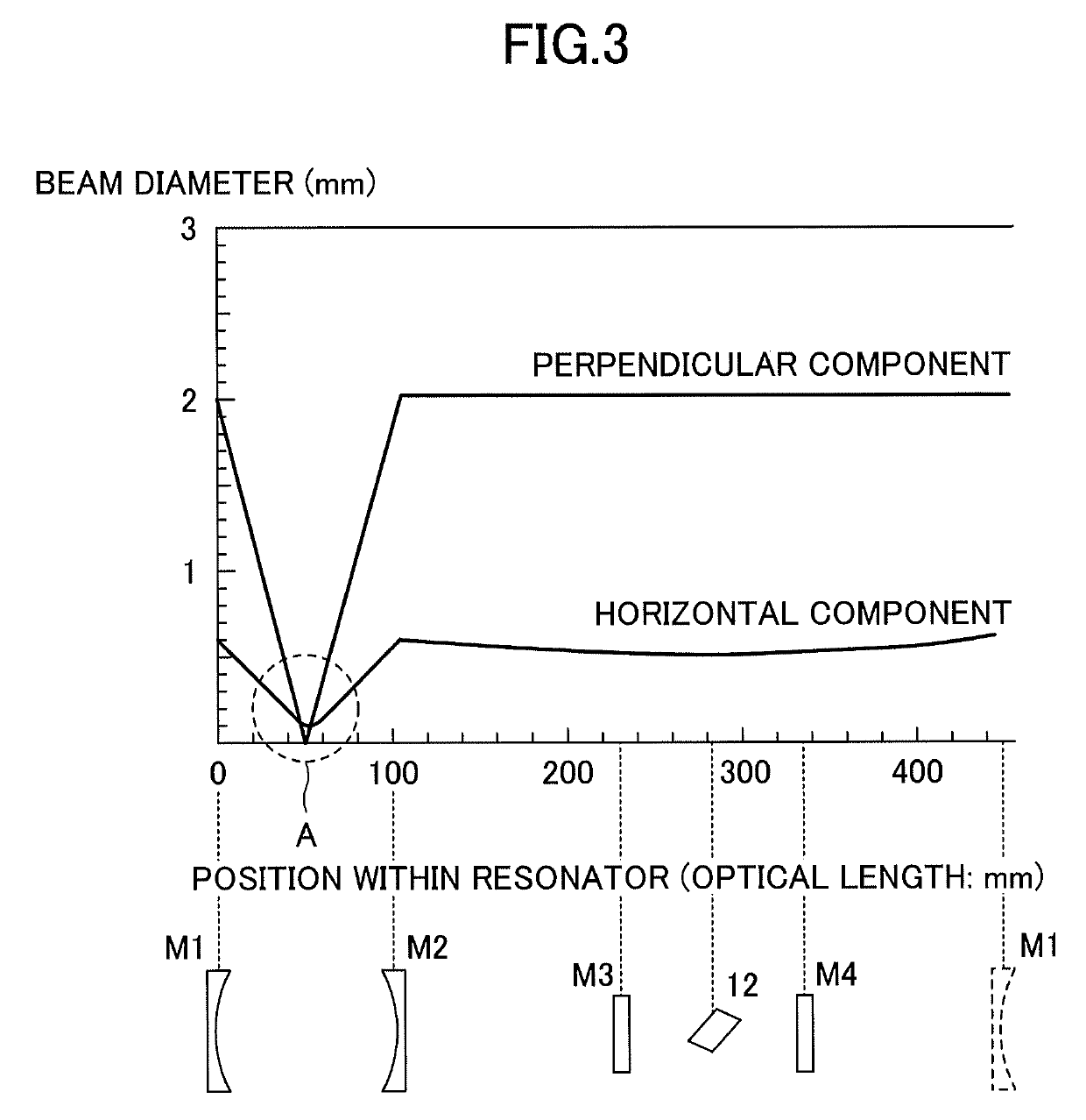
[0052]Generally, when spherical mirrors having curvature are used in the bow-tie or Z-type resonator arrangement, astigmatism occurs, the beam diameter becomes oval, and different beam divergences are generated along a major axis direction and a minor axis direction of the oval. Such different beam divergences may also be observed from FIG. 3 and FIG. 4. In order to reduce the effects of astigmatism, each of the transparent plates 15 and 16, forming an example of an astigmatism correction device or an astigmatism correction means, are inserted obliquely with respect to an optical axis. A correction amount of the astigmatism may be prescribed by a thickness t of the transparent plates 15 and 16, a refractive index...

second modification

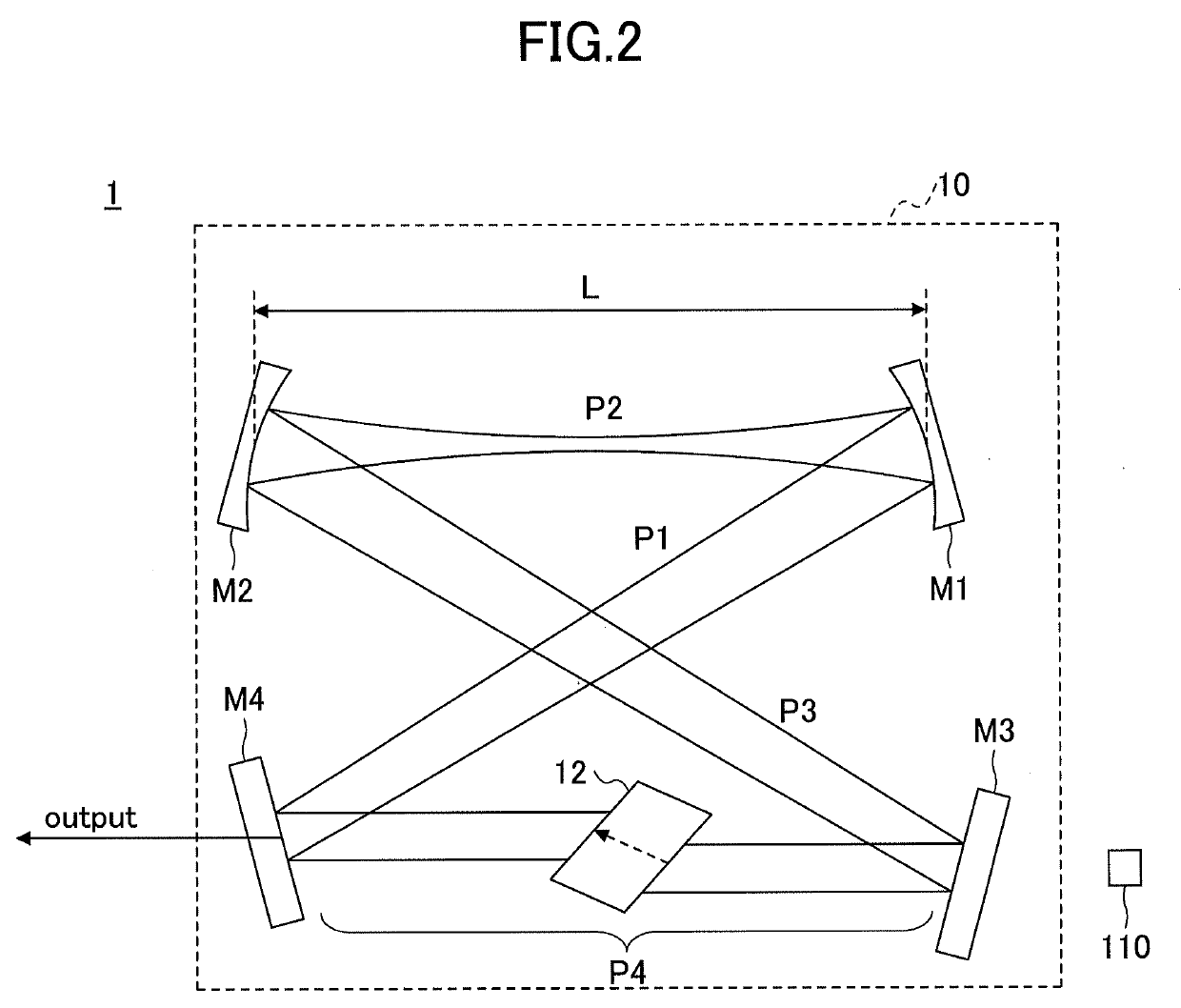
[0054]FIG. 8 is a diagram schematically illustrating a laser resonator 30 in a second modification. The configurations illustrated in FIG. 2 and FIG. 6 increases the light confinement effect by the concave mirrors M1 and M2 having the actual curvature, and also arranges the laser medium 12 in the parallel light path in which the beam diameter is large, to avoid the optical damage to the optical element or the optical component and simultaneously maintain the single transverse mode oscillation. However, the tightly focused beam waist is formed within the laser resonators 10 and 10A, and air discharge may be generated at the beam waist when the high laser output is to be obtained.

[0055]In the second modification, the beam waist region is arranged in a vacuum environment, to prevent the air discharge. The laser resonator 30 includes the concave mirrors M1 and M2 having the curvature, the planar mirrors M3 and M4, and a vacuum cell 17 arranged at the beam waist region. Similarly as in t...

third modification

[0056]FIG. 9 is a diagram schematically illustrating a laser resonator 40 in a third modification. In the third modification, the vacuum cell of the second modification and the obliquely arranged transparent plates of the first modification are combined, to prevent both the astigmatism and the air discharge. The laser resonator 40 includes the concave mirrors M1 and M2 having the curvature, the planar mirrors M3 and M4, and a vacuum cell 18 arranged at the beam waist region. The vacuum cell 18 includes transparent plates 21 and 22, respectively arranged on an incidence side and an outgoing side, and inserted obliquely with respect to the optical axis. The transparent plates 21 and 22 reduces the astigmatism, and the vacuum cell 18 prevents the air discharge. By setting the angles of the transparent plates 21 and 22 that form optical windows of the vacuum cell 18 so as to satisfy the Brewster's condition, it is possible to prevent the reflection loss. Similarly as in the case of the ...


PUM


Abstract

A laser resonator includes a pair of optical elements forming a first optical path having a focused beam waist, one or more mirrors forming a second optical path of approximately parallel light connected to the first optical path, and a laser medium arranged in the second optical path. Induced emission light generated from the laser medium reciprocates or circles in a path formed by the first optical path and the second optical path. A distance between the pair of optical elements is adjustable, and a beam diameter at the second optical path is adjusted by adjusting the distance between the pair of optical elements.

Description

CROSS-REFERENCE TO RELATED APPLICATIONS[0001]This application is a continuation application of International Application No. PCT / JP2017 / 041126 filed on Nov. 15, 2017 and designated the U.S., which is based upon and claims priority to Japanese Patent Application No. 2016-223000, filed on Nov. 16, 2016, the entire contents of which are incorporated herein by reference.BACKGROUND OF THE INVENTION1. Field of the Invention[0002]The present invention relates to a laser resonator, and a method of designing the laser resonator.2. Description of the Related Art[0003]Laser beams are used in various fields, such as optical communication, measurement of absorption and / or excitation spectrums, high-resolution measurement of matter and / or material, spectroscopy, and the like. An external cavity semiconductor laser that is highly selective and has a narrow oscillation spectral bandwidth is popularly used as a single longitudinal mode laser light source. The external cavity semiconductor laser incl...

Claims


Application Information

Patent Timeline
Patent Type & Authority Applications(United States)
IPC IPC(8): H01S3/081H01S3/08H01S3/09
CPCH01S3/0813H01S3/08018H01S3/09H01S3/0816H01S3/08045H01S3/083H01S3/08054H01S3/0805H01S3/081
Inventor KATSURAGAWA, MASAYUKIOOAE, CHIAKI
Owner UNIVERSITY OF ELECTRO-COMMUNICATIONS
Why Eureka
Try Eureka