
Self-Modifying Agitation Process And Apparatus For Support Removal In Additive Manufacturing And 3D Printed Material

a technology of additive manufacturing and agitation process, which is applied in the direction of manufacturing tools, transportation and packaging, and cleaning using liquids, etc. it can solve the problems of inability to optimize the rate of support removal, the complexity of the methods used to control the removal rate of support, and the final unwanted part in the finished form. , to achieve the effect of maximizing the removal rate, limiting the damage to the part, and enhancing the removal of suppor

Active Publication Date: 2019-09-05
POSTPROCESS TECH INC
View PDF2 Cites 9 Cited by
  • Summary
  • Abstract
  • Description
  • Claims
  • Application Information

AI Technical Summary

Benefits of technology

The present invention provides a system and method for optimizing the operation of a support removal machine. The system can accurately predict and adjust the operating parameters for a particular part, making the removal process more efficient and effective. The system also determines when and which support removal agitation component to activate, and optimizes the operation of each component for at least one consecutive time increment. The technical effects of this patent include improved efficiency and accuracy in support removal.

Problems solved by technology

An unfinished manufactured part may include portions that are necessary for manufacture or are a necessary byproduct of the manufacturing process, but which are ultimately unwanted in the finished form of the part.
Traditional methods of support removal fail to optimize the support removal rates so as to maximize operation relative to a particular manufactured part.
The methods used to control support removal are complex and may interrelate, even when applied sequentially.
In addition, there are often trade-offs between achieving a fast support removal and potential damage to the part.
Support removal has generally been limited to the use of one or two removal methods at a time, or used in systems where each removal method may have separate control systems that may be independently evaluated and adjusted on a periodic basis under controlled settings.
Furthermore, unfinished manufactured parts come in many sizes, shapes, and materials.
Existing machines and processes for support removal are prone to causing damage to the part due to over-use of a particular removal method such as heat, chemical treatment, or abrasion.
For example, excessive heat can cause weakening of delicate portions of a part, which may ultimately result in damage to the put.
And, the use of ultrasonic agitation may result in heating of the part without a corresponding temperature increase of the media in which the part resides.
The result may he an unexpected and unwanted increase in the part temperature, which results in damage to delicate portions of the part.
In short, adverse impacts may arise from numerous methods interacting with one another, thereby resulting in suboptimal application of such methods for a particular part.
Suboptimal application of any one method may lead to inefficient use of energy and / or time.
For example, excessive use of ultrasonic agitation may result in excessive heat generation and may require downtime while the system is cooled to a more optimal temperature, which takes time, and thus causes a less efficient process.
Inefficiencies can manifest themselves in the form of taking too long to fully remove support material from the part, and / or removing too much material from the part, and / or ruining the surface finish of the part.
Such losses in efficiency increase costs of operation.
Another example of an inefficiency is the suboptimal application of agitation, which can damage the part or lead to a ruined surface finish of the part.
If the intensity of the agitation is too high, or if agitation is carried out too long, the support material may be fully removed, but the surface of the part may be eroded to an undesirable extent.
The resulting parts may be unacceptable, resulting in a need to discard the part and to try again.
Compounding the problems arising from the use of conventional machines for support removal is an inability to precisely control removal methods.
By limiting a user's choice to only 100% or 0%, the result may be in an inability to optimize the process, and an increase in the potential for damage to the part.
However, traditional methods for managing multiple types of support removal methods are currently limited to (a) random application of methods, (b) manual application of methods, and (c) time-based sequencing of varying methods.
In most cases, the methods are activated based on predetermined criteria, established protocols, sequential methods, time-based approaches, operator judgment, or combinations thereof, and result in indiscriminate removal of support material, and fail to properly take into account the degree to which support material should be removed from an unfinished part.
For example, a finishing shop that uses only time-based methods will find that such methods are highly inefficient due to the wide variety of parts and materials that may be used in a particular machine.
For example, a time-based method could easily dissolve a whole part if the run time was not set properly, or some other fixed parameter was too aggressive for the particular part.
Operators of support removal machines face the difficult task of controlling process parameters that have nonlinear relationships, some of which are discussed above, while maintaining capabilities to remove support material in a timely manner.
Simultaneously optimizing heat rate, ultrasonic agitation, pH, part rotation rate, or other aspects is at best challenging, and may be unrealistic for an operator to do manually.
In addition, industry demands may impose further restrictions that impose significant restrictions on operating conditions for support removal machines and their operators.
However, such rules alone likely cannot accommodate the diverse set of operating conditions that may be encountered by operators on a daily basis.
Furthermore, time-based or random varying parameter-based systems alone may not be the best options due to the complexity of the individual parts and methods of agitation.

Method used


Image

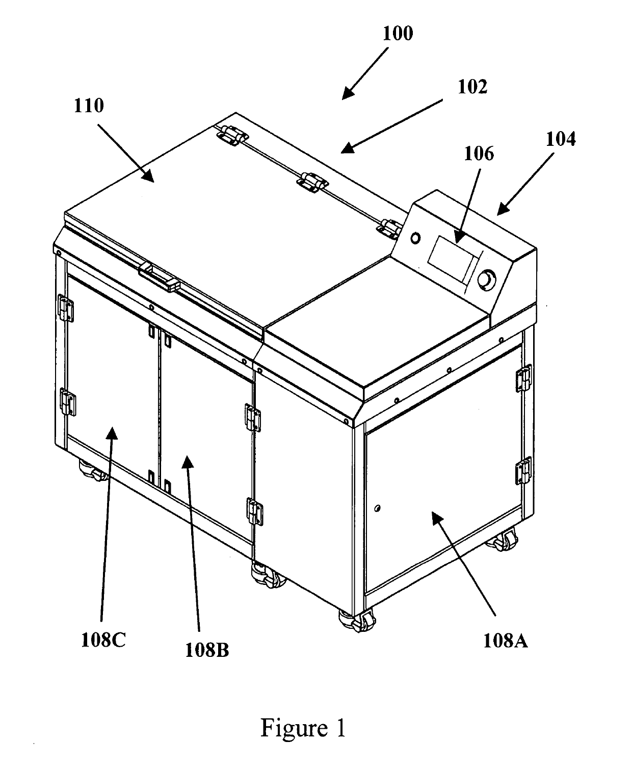
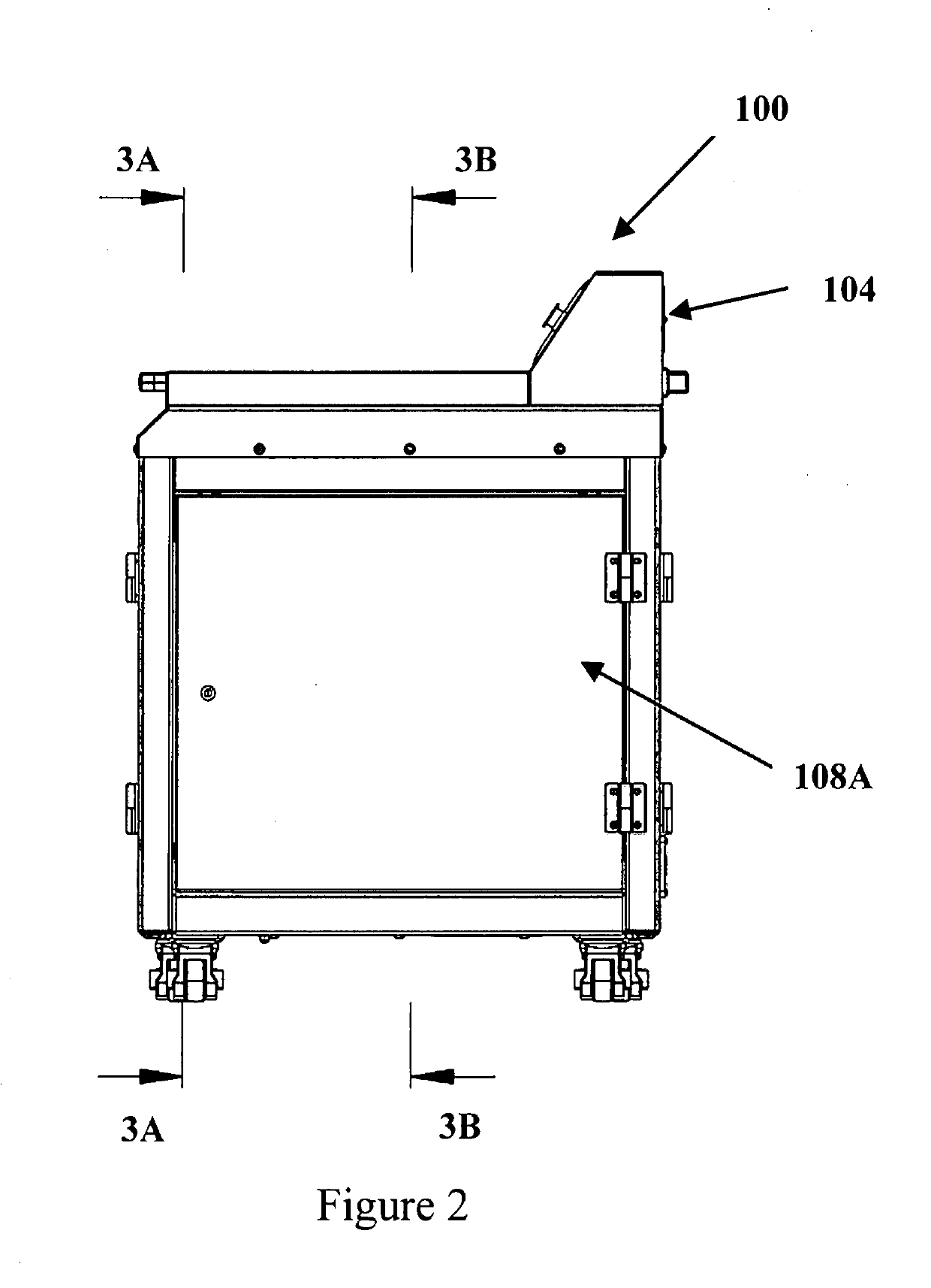
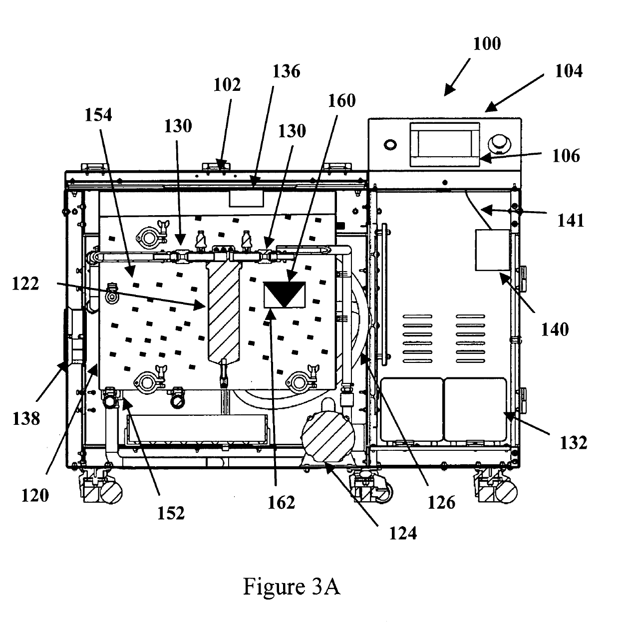
  • Self-Modifying Agitation Process And Apparatus For Support Removal In Additive Manufacturing And 3D Printed Material
  • Self-Modifying Agitation Process And Apparatus For Support Removal In Additive Manufacturing And 3D Printed Material
  • Self-Modifying Agitation Process And Apparatus For Support Removal In Additive Manufacturing And 3D Printed Material

Examples


Embodiment Construction

[0036]At the outset, it should be appreciated that like drawing numbers on different drawing views identify identical, or functionally similar, structural elements of the invention. It is to be understood that this invention is not limited to the disclosed aspects.

[0037]Furthermore, it is understood that this invention is not limited to the particular methodology, materials, or modifications described and, as such, the invention may vary from that which is disclosed herein. It is also understood that the terminology used herein is for the purpose of describing particular aspects.

[0038]Unless defined otherwise, all technical and scientific terms used herein have the same meaning as commonly understood to one of ordinary skill in the art to which this invention pertains. It should be understood that any methods, devices or materials similar or equivalent to those described herein can be used in the practice or testing of the method and apparatus.

[0039]Furthermore, as used herein, “and...


PUM

PropertyMeasurementUnit
timeaaaaaaaaaa
temperatureaaaaaaaaaa
pressureaaaaaaaaaa

Abstract

A process for support material removal for 3D printed parts wherein the part is placed in a media filled tank and support removal is optimized in a multi-parameter system through an artificial intelligence process which may include, but is not limited to, the use of historical data, parametric testing data, normal support removal data, and outputs from other support removal AI models to generate optimally efficient use of each parameter in terms of pulse repetition interval (PRI) and cycle time as defined by pulse width (PW). The input parameters may include heat, circulation, ultrasound and chemical reaction, which are used in sequence and / or in parallel, to optimize efficiency of support removal. Sequentially and / or in parallel, heat, pump circulation and ultrasound may vary in application or intensity. Selection of means of agitation depends on monitored feedback from the support removal tank and application of a statistically dynamic rule based system (SDRBS).

Description

CROSS-REFERENCE TO RELATED APPLICATION[0001]This application claims the benefit of U.S. Provisional Patent Application No. 62 / 406,187, filed Oct. 10, 2016, which application is incorporated herein by reference in its entirety and follows FIG. 8.FIELD OF THE INVENTION[0002]This invention relates generally to a method and apparatus for removing support material from unfinished manufactured parts, and, more specifically, to a method and apparatus for optimizing the support material removal process for unfinished manufactured parts Which are made using additive manufacturing techniques such as 3D printing.BACKGROUND OF THE INVENTION[0003]An unfinished manufactured part may include portions that are necessary for manufacture or are a necessary byproduct of the manufacturing process, but which are ultimately unwanted in the finished form of the part. Such portions are referred to herein as “support material” or merely as “support.” In a conventional support removal machine, an unfinished ...

Claims


Application Information

Patent Timeline
Patent Type & Authority Applications(United States)
IPC IPC(8): B29C64/35B33Y40/00B33Y50/00B29C64/386B08B3/12B24B49/14B24B49/00
CPCB29C64/35B33Y40/00B33Y50/00B24B31/10B08B3/12B24B49/14B24B49/003B29C64/386B29C64/30B08B3/102B33Y40/20Y02P10/25B29C64/118B29C71/0009B33Y30/00B33Y50/02B29C64/393B24C7/0084B24C11/005B29C64/40B29C64/379G06N3/02B01F31/80B01F31/89B01F35/90B01F2035/99
Inventor HUTCHINSON, DANIEL JOSHUA
Owner POSTPROCESS TECH INC
Learn More