Check patentability & draft patents in minutes with Patsnap Eureka AI!

Determination device and control method of determination device

a technology of determination device and control method, which is applied in the direction of measurement device, using reradiation, instruments, etc., can solve the problems of complication of the configuration itself, higher product cost and development expenses, and the inability to realize the above-described conventional technique using a general-purpose optical distance measurement module or the lik

Inactive Publication Date: 2019-09-05
ORMON CORP
View PDF0 Cites 0 Cited by
  • Summary
  • Abstract
  • Description
  • Claims
  • Application Information

AI Technical Summary

Benefits of technology

The patent is about a device that can reliably detect when someone has entered a certain distance from it, even if other distance measurement tools are used. This is useful for things like security measures.

Problems solved by technology

Therefore, it is difficult to realize the above-described conventional technique using a general-purpose optical distance measurement module or the like.
For example, there are problems such as the necessity of developing dedicated optical distance measurement IC, etc., higher product cost and development expenses, and complication of the configuration itself.

Method used


Image

  • Determination device and control method of determination device
  • Determination device and control method of determination device
  • Determination device and control method of determination device

Examples


embodiment

[0033]Hereinafter, an embodiment according to one aspect of the disclosure (hereinafter, also referred to as “the present embodiment”) will be described with reference to the drawings.

application example

§ 1 APPLICATION EXAMPLE

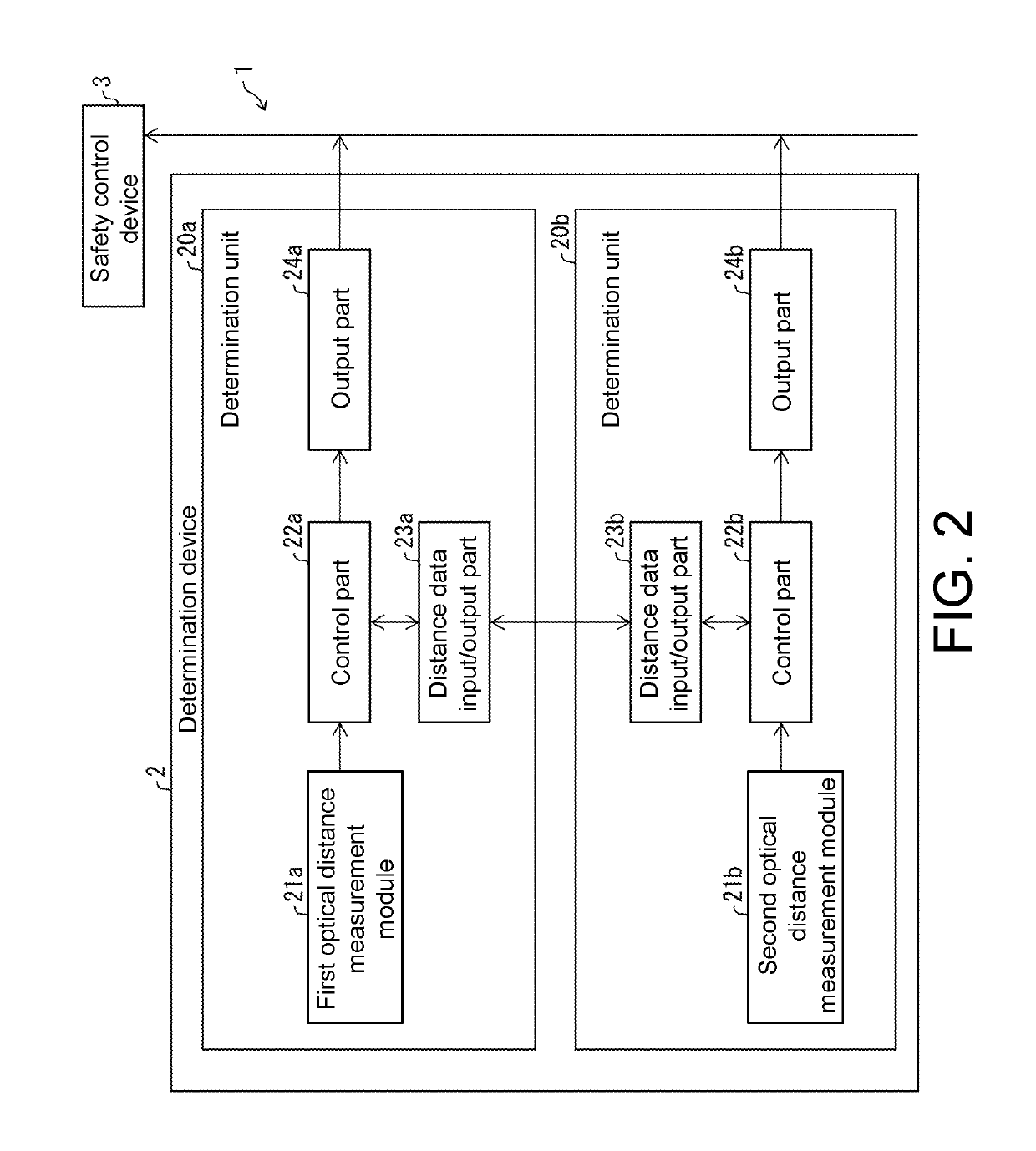
[0034]FIG. 2 is a diagram showing an example of application of a determination device 2 according to the present embodiment in a safety control system 1. First, an outline of the application example of the determination device 2 will be described with reference to FIG. 2.

[0035]The safety control system 1 is a system that stops driving a movable part, such as an end effector of a robot, before a person touches the movable part, for example, when detecting that the person approaches the periphery of the movable part. As shown in FIG. 2, the safety control system 1 includes the determination device 2 and a safety control device 3. When receiving a signal indicating intrusion detection from the determination device 2, the safety control device 3 executes safety control and performs control to stop driving the movable part such as the end effector of the robot, for example.

[0036]The determination device 2 outputs a signal indicating intrusion detection to the safet...

modified example 1

[0087]Modified examples of the disclosure will be described as follows with reference to FIG. 5 and FIG. 6. For convenience of description, members that have the same functions as those described in the above embodiment are denoted by the same reference numerals and descriptions thereof are omitted.

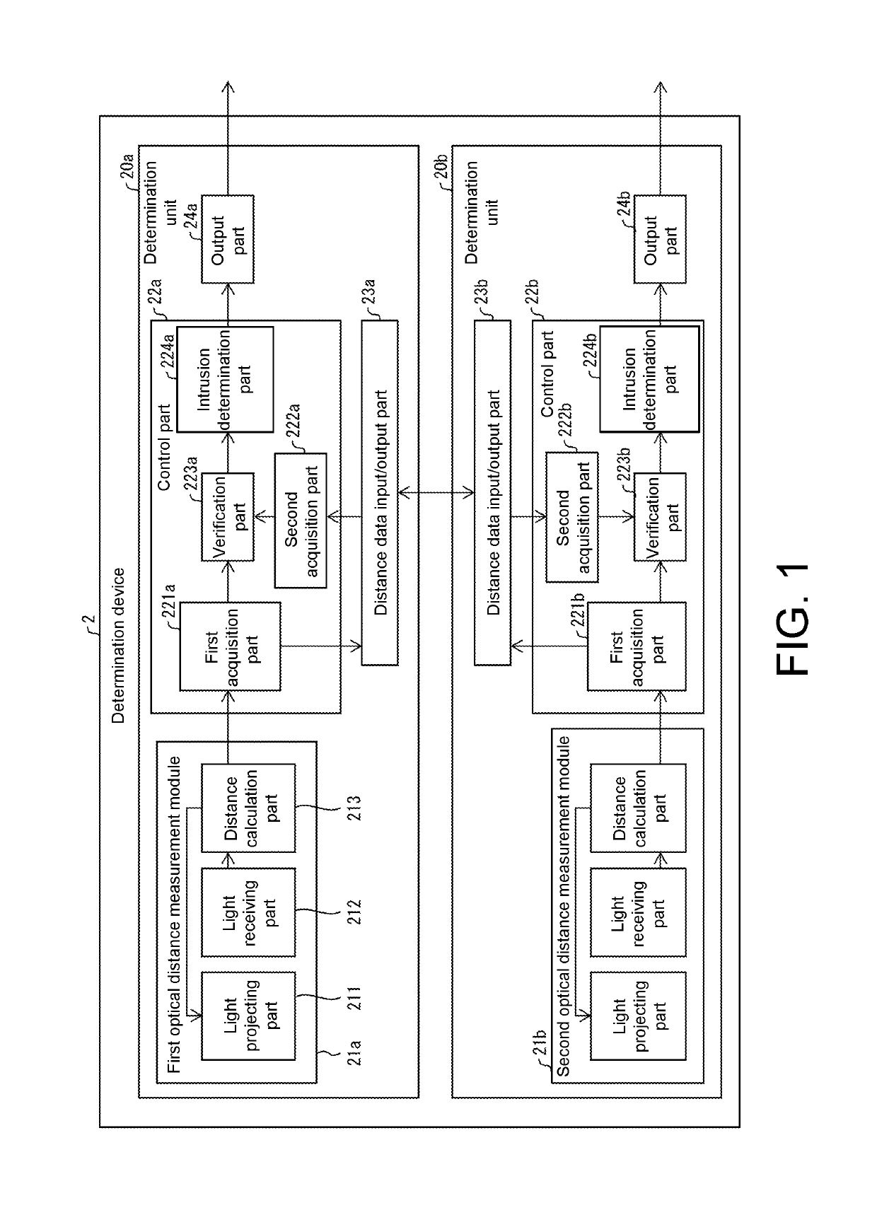
[0088]The above embodiment illustrates an example that the deteimination device 2 includes one sensor set which includes the first optical distance measurement module 21a and the second optical distance measurement module 21b.

[0089]A determination device 2c according to this modified example includes a plurality of sets of multiple optical distance measurement modules.

[0090]FIG. 5 is a diagram showing an example of application of the determination device 2c according to this modified example in a safety control system 1c. As shown in FIG. 5, the safety control system 1c includes the determination device 2c and the safety control device 3.

[0091]FIG. 6 is a diagram showing an example of an...


PUM


Abstract

The disclosure realizes a highly reliable determination device for determining the distance to an object even if general-purpose optical distance measurement modules or the like are used. The determination device determines whether at least one of the signals respectively outputted by a plurality of optical distance measurement modules indicates that the distance to the object is within a predetermined range, wherein the observation area of an optical distance measurement module is within the observation area of another optical distance measurement module.

Description

CROSS-REFERENCE TO RELATED APPLICATION[0001]This application claims the priority benefit of Japanese Patent Application serial no. 2018-036809, filed on Mar. 1, 2018. The entirety of the above-mentioned patent application is hereby incorporated by reference herein and made a part of this specification.BACKGROUNDTechnical Field[0002]The disclosure relates to a determination device that outputs a signal indicating intrusion detection when the distance to an object is within a predetermined range.Description of Related Art[0003]As a device for measuring the distance to a detected object based on the ToF (Time of Flight) principle, for example, Patent Document 1 (Specification of US Patent Application Publication No. 2016 / 0327649 (Nov. 10, 2016)) discloses an optical distance measurement module that emits light to the detected object with a light emitting element, reads the reflected light with a light receiving element, and performs distance calculation.[0004]When the optical distance ...

Claims


Application Information

Patent Timeline
IPC IPC(8): G01S17/02G01S17/08G01S17/04G01S17/18
CPCG01S17/08G01S17/026G01V8/20G01S17/88G08B13/183G08B13/19682G01S17/18G01S5/16G08B15/00G01S17/04G01S17/06G01S17/48
Inventor AKAGI, TETSUYA
Owner ORMON CORP
Features
  • R&D
  • Intellectual Property
  • Life Sciences
  • Materials
  • Tech Scout
  • Unparalleled Data Quality
  • Higher Quality Content
  • 60% Fewer Hallucinations
Learn More