Check patentability & draft patents in minutes with Patsnap Eureka AI!

Method for measuring digging positions

a technology for digging positions and positioning positions, applied in the field of measuring digging positions, can solve the problem of not being able to achieve a highly reliable determination of digging positions, and achieve the effect of high-reliability determination of digging positions

Inactive Publication Date: 2005-03-22
KDDI CORP
View PDF2 Cites 2 Cited by
  • Summary
  • Abstract
  • Description
  • Claims
  • Application Information

AI Technical Summary

Benefits of technology

This method enables highly reliable determination of the digging position by isolating the signal magnetic field from noise, ensuring accurate positioning even in the presence of power lines or other magnetic noise sources, thereby improving the precision and reliability of horizontal drilling operations.

Problems solved by technology

The method is defective in that it is unable to achieve a highly reliable determination of the digging position when a power line or similar magnetic noise source is present in or around the place where the position determination is to be performed.

Method used


Image

  • Method for measuring digging positions
  • Method for measuring digging positions
  • Method for measuring digging positions

Examples


Embodiment Construction

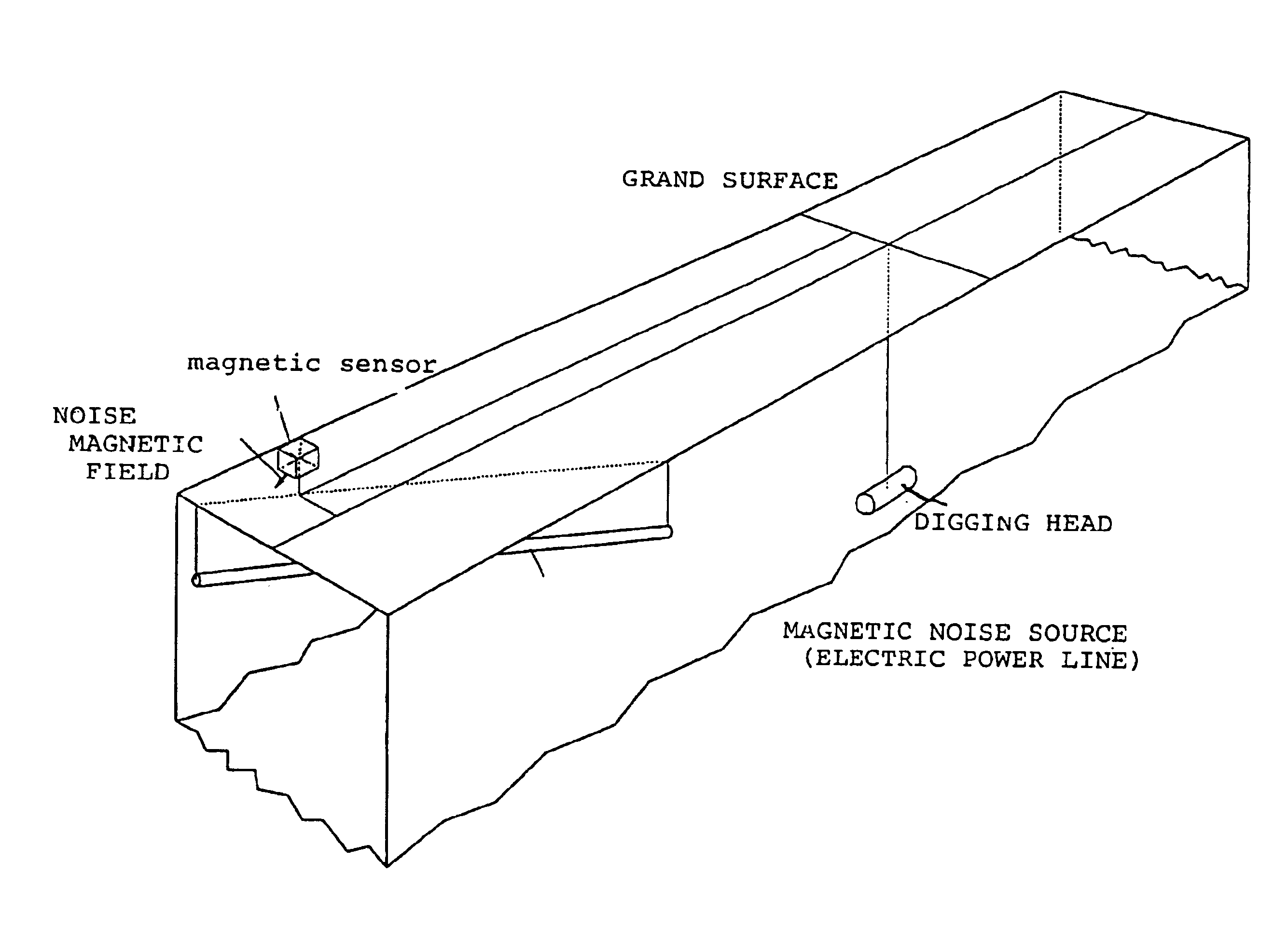
As depicted in FIG. 1, the position of a digging head 2 under the ground surface 1, which creates a signal magnetic field source to be sensed, is determined using a magnetic sensor 4 placed on the ground surface 1 at a proper position at the same time that a power line or similar magnetic noise source 3, which generates a noise magnetic field, is placed near the digging position to be determined. More specifically, a signal magnetic field vector Hs is provided from the digging head 2 and a noise magnetic field vector Hn is provided from the magnetic noise source 3, such as power line. In this case, the magnetic sensor 4 senses a resulting vector Hm that is a combined version of the signal magnetic field vector Hs and the noise magnetic field vector Hn.

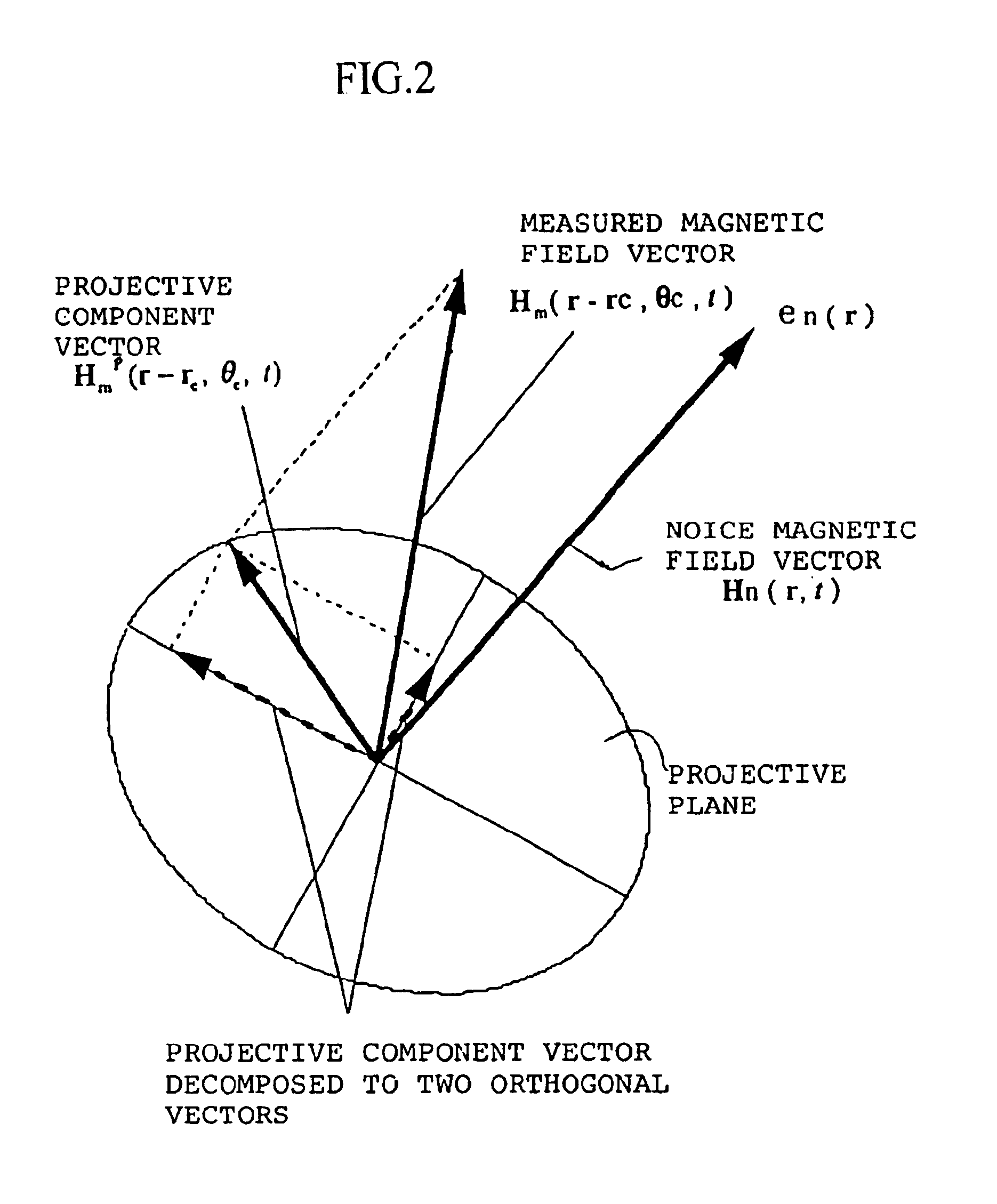
Referring to FIG. 2, a noise magnetic field of a position vector r and at tie t is identified as a vector Hn(r, t). On the other hand, the signal magnetic field generated by magnetic field generating means for position sensing is ident...


PUM


Abstract

A method for determining position is disclosed, one that is highly reliable in determining a digging position. This method involves the capacity to sense, on the ground, an AC magnetic field generated by a coil housed in a digging head even when there are other noise magnetic fields present that could affect position determination. This method is used in a non-open-cut (boring or trenching) dig. It senses the senses the AC magnetic field provided from a magnetic field source by means of an above-ground magnetic sensor and calculates the position of the magnetic field source from the magnitude and direction of the sensed AC magnetic field. When another noise magnetic field is generated by a nearby current, the magnetic field sensed by the magnetic sensor is projected onto a flat plane or straight line orthogonal to a vector-valued direction of the noise magnetic field, and the projective component is used to calculate the following: at least one position of the magnetic field source; the tilt angle of the magnetic field source, its inclination to the vertical direction; and the azimuth direction of the magnetic field source, its axial direction in a horizontal plane.

Description

BACKGROUND OF INVENTION1. Field of the InventionThe present invention relates to a method of determining the digging position of a digging head in a substantially horizontal digging or excavation and, more particularly, to a method that ensures accuracy in determining positions of the digging head by lessening the influence of noise magnetic field frequency components close to the signal magnetic field to be measured.2. Brief Description of the Prior ArtA horizontal drilling method, which is one of the boring or trenching methods of this kind, uses a small-diameter pipe of 100 mm or less for horizontally digging in the ground, and, accordingly, the kind of precision position-determining apparatus used in an ordinary small-diameter driving method of excavation cannot be placed near a drill. To solve this problem, it is customary in the art to generate an AC magnetic field by means a coil mounted in the drill head that is detected by an above-ground magnetic sensor like a coil to dete...

Claims


Application Information

Patent Timeline
Patent Type & Authority Patents(United States)
IPC IPC(8): E21B47/022E21B47/02G01V3/08
CPCG01V3/081E21B47/02224E21B47/0232
Inventor MATSUMOTO, SHIGETAKA
Owner KDDI CORP
Features
  • R&D
  • Intellectual Property
  • Life Sciences
  • Materials
  • Tech Scout
  • Unparalleled Data Quality
  • Higher Quality Content
  • 60% Fewer Hallucinations
Learn More