Polyaxial bone anchoring device and system including an instrument and a polyaxial bone anchoring device

Active Publication Date: 2019-09-12
BIEDERMANN TECH GMBH & CO KG
View PDF0 Cites 3 Cited by
  • Summary
  • Abstract
  • Description
  • Claims
  • Application Information

AI Technical Summary

Benefits of technology

[0009]The locking and unlocking of the head during surgery can also be carried out with the rod not yet inserted or being at an elevated position in the receiving part away from the bottom of the rod receiving recess. This increases the possibilities of carrying out correction steps during surgery.
[0010]Moreover the locking and unlocking of the head can be effected independently from the fixation of the rod. Hence, the locking of the head can be maintained while adjustments on the posit

Problems solved by technology

Locking of the head is achieved by clamping with such a force

Method used


Image

  • Polyaxial bone anchoring device and system including an instrument and a polyaxial bone anchoring device
  • Polyaxial bone anchoring device and system including an instrument and a polyaxial bone anchoring device
  • Polyaxial bone anchoring device and system including an instrument and a polyaxial bone anchoring device

Examples


first embodiment

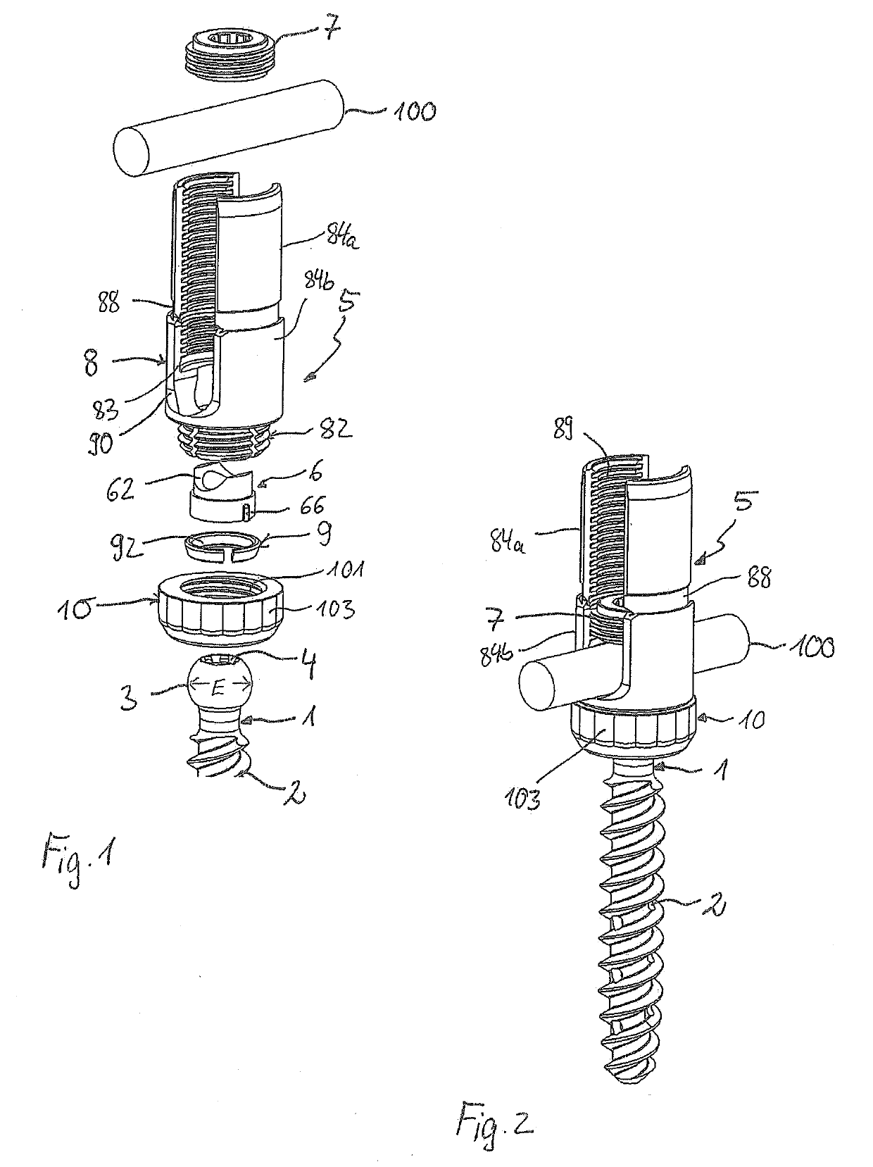
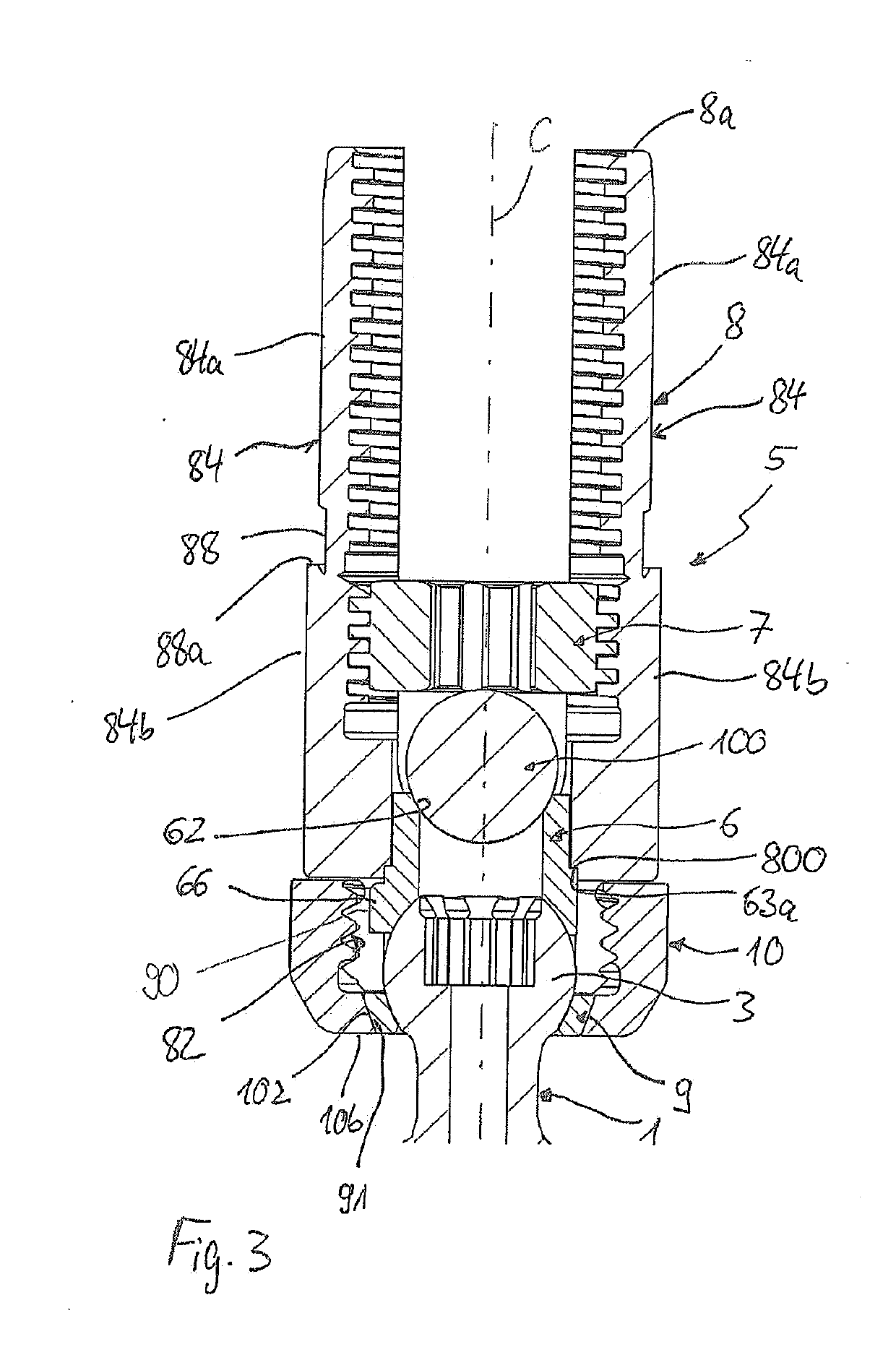
[0062]As shown in FIGS. 1 to 3, a polyaxial bone anchoring device includes a bone anchoring element 1 in the form of a bone screw having a shank 2 with a threaded portion and a head 3 having a spherically shaped outer surface portion. The head 3 has a largest diameter E and a recess 4 for engagement with a screwdriver at a free end surface. The bone anchoring device further includes a receiving part 5 for receiving the head of the anchoring element 1 and for receiving a rod 100 in order to couple the bone anchoring element 1 to the rod 100. In the receiving part 5, a pressure member 6 is arranged for exerting pressure onto the head 3 when the head 3 is inserted into the receiving part 5. In addition, the bone anchoring device includes a fixation element 7 for securing the rod 100 and for locking the head 3 in the receiving part 5.

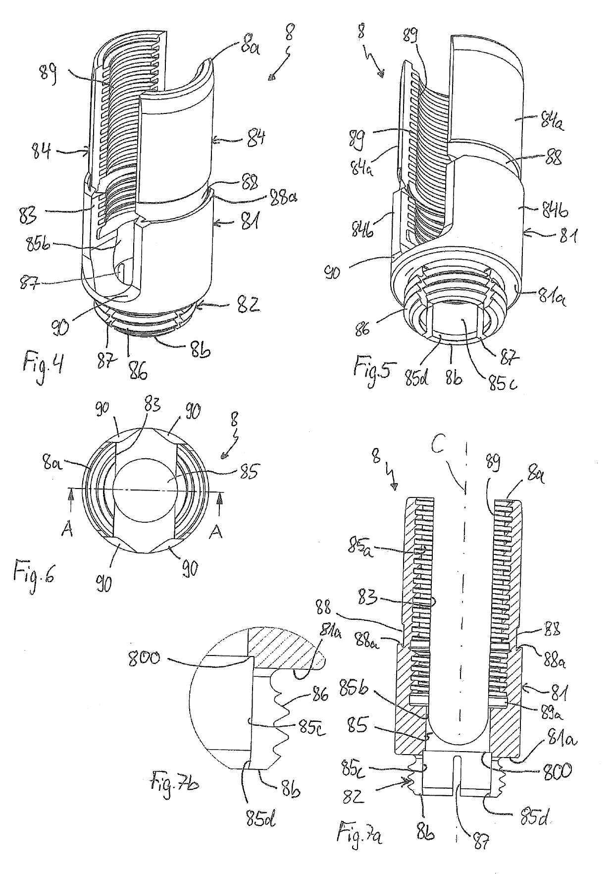
[0063]As shown in FIG. 1, the receiving part 5 is a two part piece with an upper member 8 and a lower member 10 that is connectable to the upper member 8....

second embodiment

[0095]The bone anchoring device of the second embodiment may be pre-assembled in a manner such that the pressure member 6′ is inserted into the upper member 8′ and the lower member 10′ is connected to the upper member 8′. The bone anchoring element 1 can thus be inserted from the bottom end 10b of the lower member 10′ into the receiving part 5′.

[0096]FIGS. 43a to 43d show steps of use of the bone anchoring device according to the second embodiment, in connection with the instrument. The instrument with the inner sleeve 200 and outer sleeve 300 as described in connection with FIGS. 20 to 25 can be used. The instrument can be attached to the assembled bone anchoring device with inserted rod 100 and fixation member 7 (see FIG. 43a) by downward movement of the respective front portions (see FIG. 43b), until the inner sleeve 200 engages the upper member 8′ in a rotationally fixed manner and the outer sleeve 300 engages the engagement structure 103 on the outer surface of the lower member...


PUM


Abstract

A polyaxial bone anchoring device includes a receiving part with an upper member having a first end, a second end, and a recess at the first end for receiving a rod, and a lower member connectable around the second end of the upper member, and a pressure member positionable in the upper member to exert pressure on a head of a bone anchoring element. The lower member is movable from a first position where the head is pivotable, to a second position closer to the first end of the upper member where an angular position of the head is locked while the recess remains vacant or unobstructed. When the lower member is at the second position, at least part of the lower member is aligned axially with at least part of an end face at the second end of the upper member.

Description

CROSS-REFERENCE TO RELATED APPLICATION(S)[0001]The present application claims priority to and the benefit of U.S. Provisional Patent Application No. 62 / 639,224, filed Mar. 6, 2018, the contents of which are hereby incorporated by reference in their entirety, and claims priority from European Patent Application EP 18 160 167.5, filed Mar. 6, 2018, the contents of which are hereby incorporated by reference in their entirety.BACKGROUND[0002]The application relates to a polyaxial bone anchoring device and a system including a polyaxial bone anchoring device and an instrument for use with the device. More specifically, the bone anchoring device includes a receiving part for coupling a rod to a bone anchoring element and a pressure member for exerting pressure onto an inserted head of the bone anchoring element. The receiving part includes an upper member and a lower member that can be mounted together to clamp the head.Description of Related Art[0003]WO 2011 / 077511 A1 describes a spine f...

Claims


Application Information

Patent Timeline
IPC IPC(8): A61B17/70
CPCA61B17/7037A61B17/7076A61B2017/564A61B17/7032A61B17/7002A61B17/7091A61B17/7077A61B2017/00831A61B17/7035A61B2090/037
Inventor BIEDERMANN, LUTZBIEDERMANN, TIMOFISCHER, BERND
Owner BIEDERMANN TECH GMBH & CO KG
Why Eureka
Try Eureka