
Epicardial ablation catheter and method of use

a catheter and endocardial ablation technology, applied in the field of medical implants, can solve the problems of inconvenient use, injury to patients, awkwardness of conventional long catheters used in endocardial ablation, etc., and achieve the effect of preventing hemodynamic collapse and death

Pending Publication Date: 2019-09-12
UNIV OF VIRGINIA ALUMNI PATENTS FOUND
View PDF0 Cites 9 Cited by
  • Summary
  • Abstract
  • Description
  • Claims
  • Application Information

AI Technical Summary

Benefits of technology

The present invention provides a safer and easier to use method for accessing the heart for ablation procedures. By using a shorter sheath and catheter, there is less risk of injury to the patient and easier handling. Additionally, the invention prevents the need for longer catheters that may be less stable and safe. Another advantage is the use of suction to remove excess fluid, which can prevent cardiac collapse and death in cases of perforation.

Problems solved by technology

Similarly, sheaths in excess of the required 30 cm could be an awkward physical obstacle that would interfere with the procedure and, if inadvertently bumped or moved, could injure the patient.
Similarly the conventional long catheters used in endocardial ablation, while not dangerous as such, are nevertheless awkward.

Method used


Image

  • Epicardial ablation catheter and method of use
  • Epicardial ablation catheter and method of use
  • Epicardial ablation catheter and method of use

Examples


examples

[0077]Practice of the invention will be still more fully understood from the following examples, which are presented herein for illustration only and should not be construed as limiting the invention in any way.

example no.1

Example No. 1

[0078]Summary of Dual-Deflectable Irrigated / Suction-Tip Ablation Catheter is provided below.

[0079]Some non-limiting exemplary design features of the ablation catheter are:

[0080](1) A length of 90 cm, with an 8 Fr diameter.

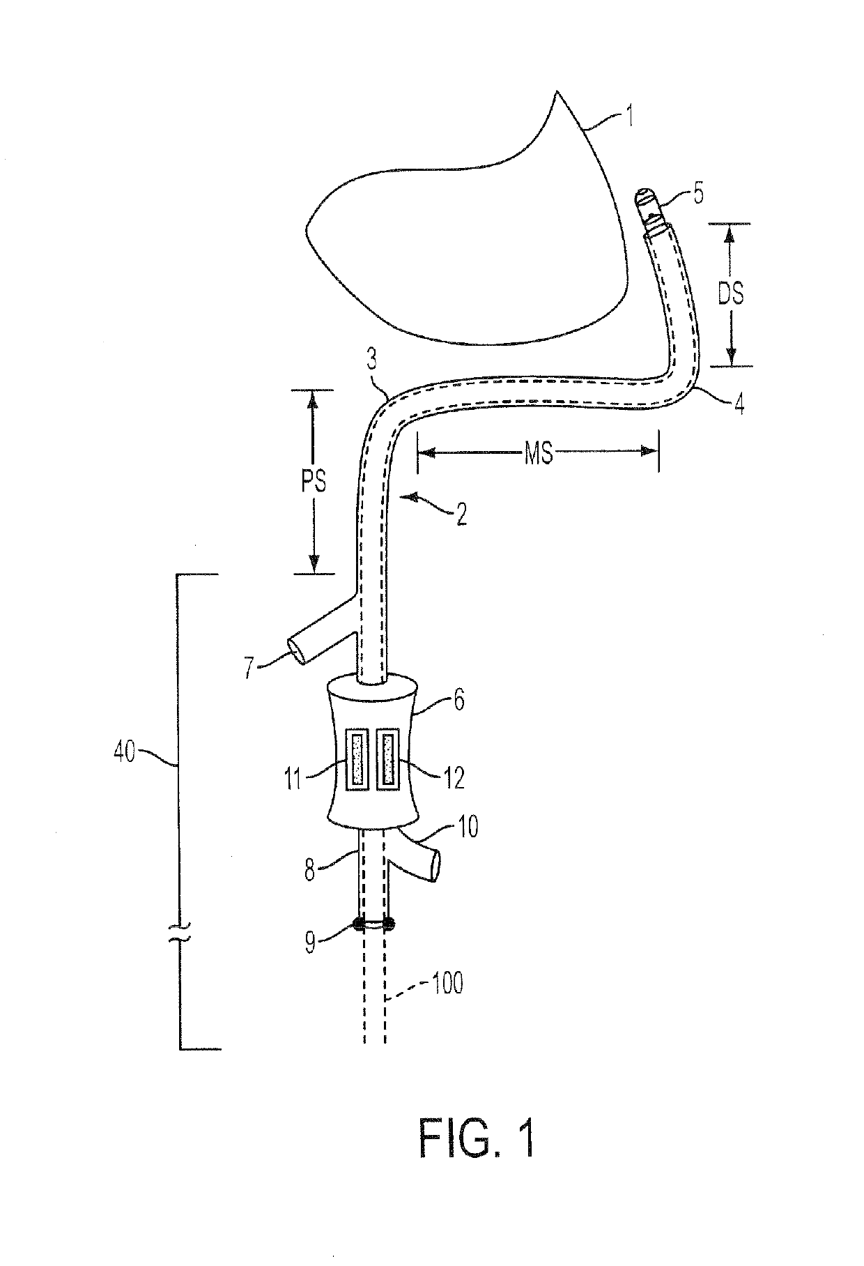
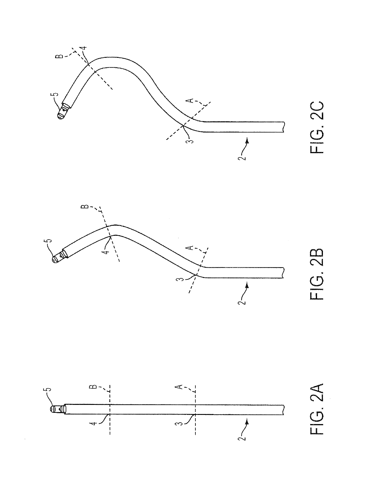
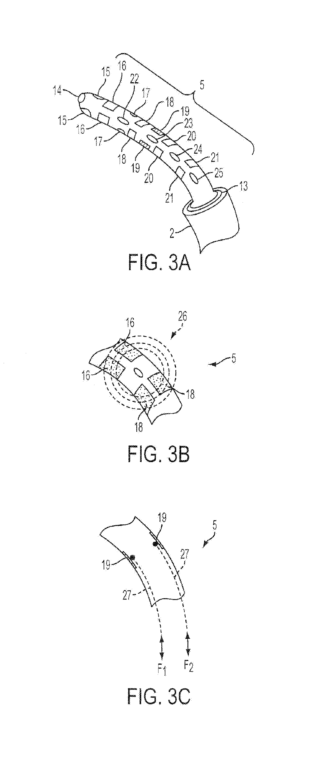
[0081](2) Two separate deflectable points. At rest the catheter will be straight. However the distal tip can be deflected through 120 degrees in two directions, approximately 17 mm from the tip. A second deflectable curve will be centered approximately 50 mm proximal to the tip and will be able to deflect through 120 degrees in one direction. The nominal 50 mm length could be variable to create a family of catheters, so that shorter curves would be used in small children while longer curves would be used in larger adults.

[0082](3) Irrigation on the entire end of the catheter with suction at three points just proximal to the second set of electrodes so all sides of the catheter tip are kept cool but the irrigation fluid is sucked back. In addition there...

example no.2

Example No. 2

[0089]In one embodiment, the conductor resistance for anodes and cathodes would be 0.9 Ohms (static). Irrigation would take place at 4 PSI, and suction at 3 PSI. The ablation system would provide electromagnetic shielding, with room for guidance means and / or propulsion means. The ablation catheter would be stiff enough for use in a robotic system, such as the Hansen Sensei system, with a 6.5 Fr outer size and a length of 55 cm. Various robotic systems would provide a means for navigating the ablation catheter and related components disclosed herein.


PUM


Abstract

An aspect of various embodiments of the present invention system and method provide, but not limited thereto, a novel means for epicardial ablation using a double-curve steerable sheath and a double-curve deflectable open irrigated-tip / suction catheter that can be guided around the apex of the heart and adjusted so as to position the distal tip optimally. The catheter can also both deliver fluid to and withdraw fluid from the pericardial space. Access to the epicardial surface of the heart is via a subxiphoid entry. The method and means presented include, but are not limited to, steering, energy delivery, bipolar mapping, placement and use of electrodes, irrigation, suction of irrigation fluid, and other details of the subject invention.

Description

RELATED APPLICATIONS[0001]The present application is a continuation application of U.S. application Ser. No. 12 / 530,938, filed Sep. 11, 2009, which is a national stage filing of International Application No. PCT / US2008 / 056816, filed Mar. 13, 2008, which claims priority under 35 U.S.C. § 119(e) from U.S. Provisional Application Ser. No. 60 / 906,689 filed Mar. 13, 2007, entitled “Epicardial Ablation Catheter and Access Sheath and Method of Use,” the disclosures of which are hereby incorporated by reference herein in their entireties.[0002]This application is related to International Application No. Serial No. PCT / US2008 / 056643, filed Mar. 12, 2008, entitled, “Access Needle Pressure Sensor Device and Method of Use,” (and its corresponding U.S. National Stage application Ser. No. 12 / 530,830, filed Sep. 11, 2009, now U.S. Pat. No. 8,282,565) which claims benefit under 35 U.S.C. § 119(e) of priority from U.S. Provisional Application Ser. No. 60 / 918,782, filed Mar. 19, 2007, entitled “Manom...

Claims


Application Information

Patent Timeline
IPC IPC(8): A61B18/14
CPCA61B2018/00577A61B2218/002A61B2018/00011A61B2018/00029A61B18/1492A61B2218/007A61B2018/00363A61B2018/00035A61B2018/00791A61B2018/1467A61M25/0133A61M25/0147A61M25/0662A61M2025/0681
Inventor MAHAPATRA, SRIJOYGILLIES, GEORGE T.
Owner UNIV OF VIRGINIA ALUMNI PATENTS FOUND
Learn More