
Stand-Alone Interbody Fusion

a technology of interbody fusion and fusion plate, which is applied in the field of spinal fusion implants, can solve the problems of easy removal of implants, and achieve the effects of improving the overall short-term and long-term stability of implants, improving the fixation or stabilization of implants, and reducing patients' pain

Inactive Publication Date: 2019-09-12
NEXUS SPINE L L C
View PDF0 Cites 10 Cited by
  • Summary
  • Abstract
  • Description
  • Claims
  • Application Information

AI Technical Summary

Benefits of technology

The invention provides an improved way to fix and stabilize implants in the body. Instead of using separate fixation devices, the implant has deployable spikes or anchors that are nested or collapsed during insertion and can be moved perpendicular to the implant's direction of insertion. The anchors secure the implant in place and reduce pain and complications. The implant can also be easily removed for revision surgery. Overall, this technology improves the stability and integration of the implant with the patient's body.

Problems solved by technology

Accordingly, removal of the implant becomes much easier than with traditional implant fixation systems, as traditional fixation systems may require significant destruction of surrounding bony structures to obtain removal of the implant with its traditional fixation devices.

Method used


Image

  • Stand-Alone Interbody Fusion
  • Stand-Alone Interbody Fusion
  • Stand-Alone Interbody Fusion

Examples


Embodiment Construction

[0059]A description of embodiments of the present invention will now be given with reference to the Figures. It is expected that the present invention may take many other forms and shapes, hence the following disclosure is intended to be illustrative and not limiting, and the scope of the invention should be determined by reference to the appended claims.

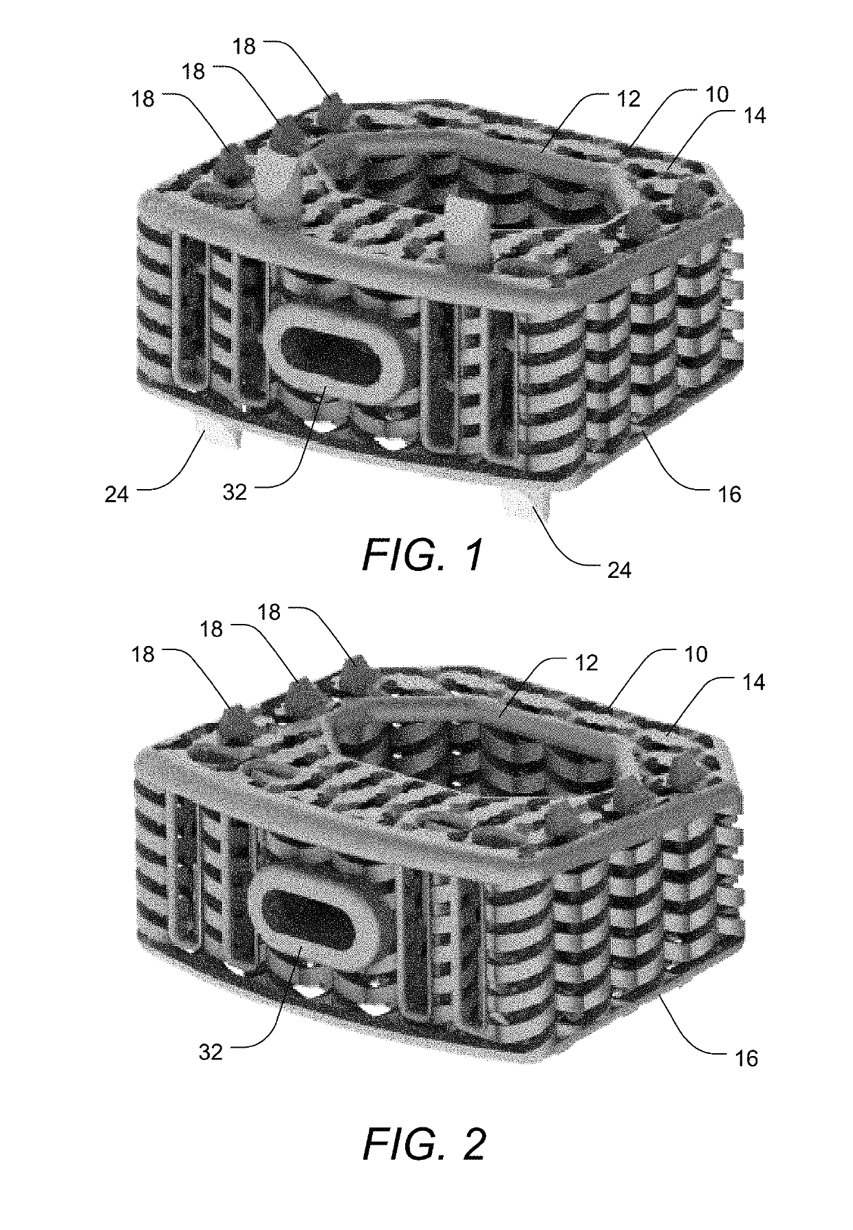
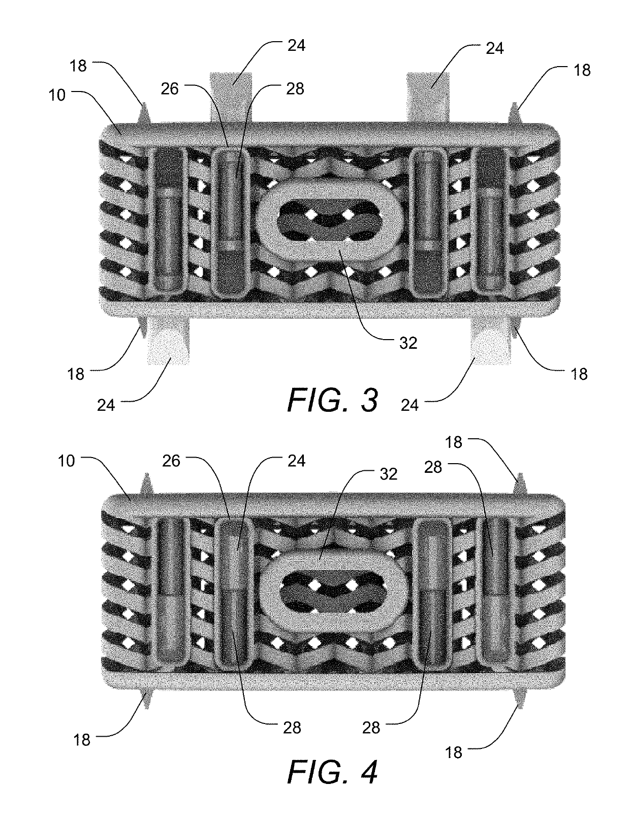
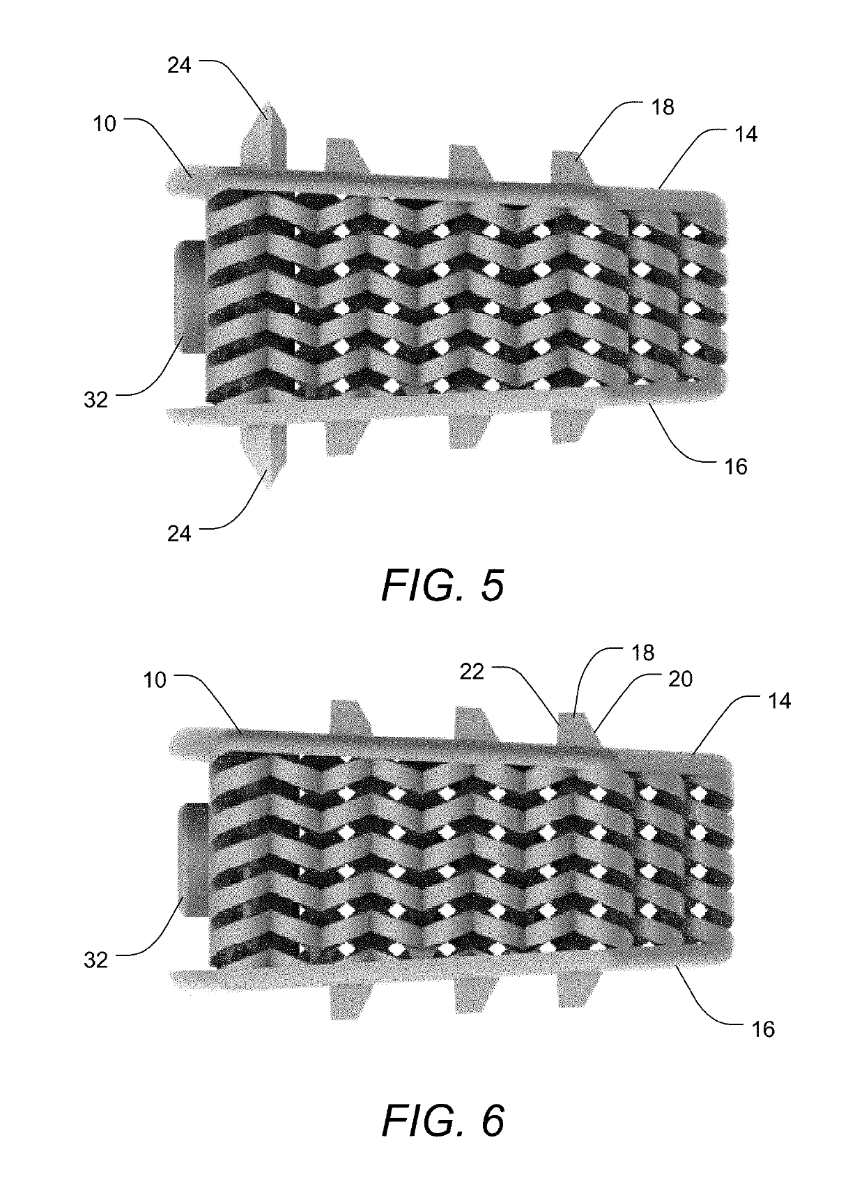
[0060]Embodiments of the invention provide improved fixation or stabilization of implants via one or more deployable spikes or anchors. The deployable spikes or anchors may be present in the implant in a nested, collapsed, or retracted position while the implant is inserted into the human body, and may then be deployed (e.g., into adjacent bone) after the implant is in place, thereby fixing the implant's location against unwanted movement. Such fixation or stabilization of the implant may reduce patients' pain, may improve overall short-term and long-term stability of the implant, and may improve osteo-integration into the implant.

[...


PUM


Abstract

Improved fixation or stabilization of implants is achieved via one or more deployable spikes or anchors. The deployable spikes or anchors may be present in the implant in a nested, collapsed, or retracted position while the implant is inserted into the human body, and may then be deployed (e.g., into adjacent bone) after the implant is in place, thereby fixing the implant's location against unwanted movement. Such fixation or stabilization of the implant may reduce patients' pain, may improve overall short-term and long-term stability of the implant, and may improve osteo-integration into the implant.

Description

CROSS-REFERENCE TO RELATED APPLICATIONS[0001]This application claims the benefit of U.S. Provisional Application No. 62 / 640,556, filed Mar. 8, 2018, U.S. Provisional Application No. 62 / 689,703, filed Jun. 25, 2018, and U.S. Provisional Application No. 62 / 689,707, filed Jun. 25, 2018, each of which is incorporated herein by reference in their entireties for all they disclose.[0002]This application is related to U.S. patent application Ser. No. 15 / 372,290, filed Dec. 7, 2106, which is incorporated herein by reference for all it discloses.BACKGROUND OF THE INVENTION1. Field of the Invention[0003]The present invention relates to spinal fusion implants, and more particularly to a porous interbody spacer having features increasing stabilization of the implants in the disc space.2. Background and Related Art[0004]Human bones are generally formed of two types of structural bone tissue: cortical bone and trabecular or cancellous bone. Cortical bone generally forms the outer shell of most bon...

Claims


Application Information

Patent Timeline
IPC IPC(8): A61F2/44A61F2/30A61F2/46
CPCA61F2002/30622A61F2/4455A61F2002/30283A61F2/4611A61F2002/30892A61F2/30749A61F2002/30848A61F2002/30579A61F2/442A61F2/447A61F2002/30841A61F2002/30891A61F2002/3028A61F2002/30593A61F2002/30845
Inventor HAWKES, DAVIDHALVERSON, PETERHARRIS, JEFFREY ELLISHOSKINS, JEFFREY S.
Owner NEXUS SPINE L L C
Learn More