Transparent ceramics, manufacturing method thereof, and magneto-optical device

a technology of transparent ceramics and manufacturing methods, applied in the field of transparent ceramics, manufacturing methods thereof, and magneto-optical devices, can solve the problems of difficult to achieve a high transmittance of at least 80%, difficult to uniformly mix the main component and the sintering aid, and achieve the effect of reducing rgd scattering

Active Publication Date: 2019-09-12
SHIN ETSU CHEM IND CO LTD
View PDF1 Cites 6 Cited by
  • Summary
  • Abstract
  • Description
  • Claims
  • Application Information

AI Technical Summary

Benefits of technology

[0032]The method for manufacturing a transparent ceramic material in the form of a cubic (C type) rare earth complex oxide sintered body includes the sintering step and the HIP step, wherein the heating rate up to the predetermined temperature T1 in the sintering step is high while the sintering temperature T is kept relatively low, and the HIP temperature of the HIP step is kept relatively low. A sintered body containing crystal grains with a grain size of up to 2 μm and having a density of at least 95% is obtained, thereby reducing RGD scattering due to a compositional variation among crystal grains. The transparent ceramic material functions as an optical part in a broad range from visible to NIR.

Problems solved by technology

However, of actual transparent ceramics, few ceramics are composed solely of the main component, because additives such as sintering aid are mostly added.
Particularly when the difference in ionic radius between elements of the main component and the sintering aid exceeds 15%, it is difficult to uniformly mix the main component and the sintering aid.
However, since the RGD scattering due to a difference of refractive index between grains is also affected by grain size, it is not concluded that better results are always obtainable from large crystal grains.
Because of the non-uniform distribution of the sintering aid, it is difficult to obtain a high transmittance of at least 80%.
Then the ceramic is difficult to use as magneto-optical parts for light of wavelength 532 nm.

Method used


Image

  • Transparent ceramics, manufacturing method thereof, and magneto-optical device
  • Transparent ceramics, manufacturing method thereof, and magneto-optical device

Examples


example 1

Example 1-1

[0114]Terbium oxide powder (Tb4O7, purity ≥99.9 wt %) and yttrium oxide powder (Y2O3, purity ≥99.9 wt %), both available from Shin-Etsu Chemical Co., Ltd., were weighed in such amounts totaling to 50 g that a molar ratio of Tb:Y was 50:50. These powders and 0.2 g (corresponding to 0.5% by weight, calculated as oxide, of the sintering aid) of a zirconia precursor to serve as a sintering aid (compositional formula: ZrOCl2, purity 99.9 wt %, by Daiichi Kigenso Kagaku Kogyo Co., Ltd.) were dissolved in 200 ml of an acidic solution (compositional formula: HNO3, concentration: 43 wt %, by Wako Pure Chemical Corp.). Then a basic solution (compositional formula: NH3, concentration: 23 wt %, by Wako Pure

[0115]Chemical Corp.) was added dropwise to the solution whereupon a substantially insoluble hydroxide salt precipitated. The hydroxide salt thus precipitated was collected on a Buchner funnel and fired in oxygen atmosphere at 1,000° C. for 3 hours, obtaining terbium-containing oxi...

examples 1-2 to 1-10

and Comparative Examples 1-1 to 1-8

[0133]Secondary sintered body samples were manufactured under the same conditions as in Example 1-1 except that at least any one of the heating rate up to the predetermined temperature T1, sintering temperature T, and HIP temperature was changed. In Comparative Examples 1-3 and 1-4, the sintering temperature T was 1,200° C. and the heating rate up to 1,200° C. was a constant rate of 100° C. / h and 200° C. / h, respectively.

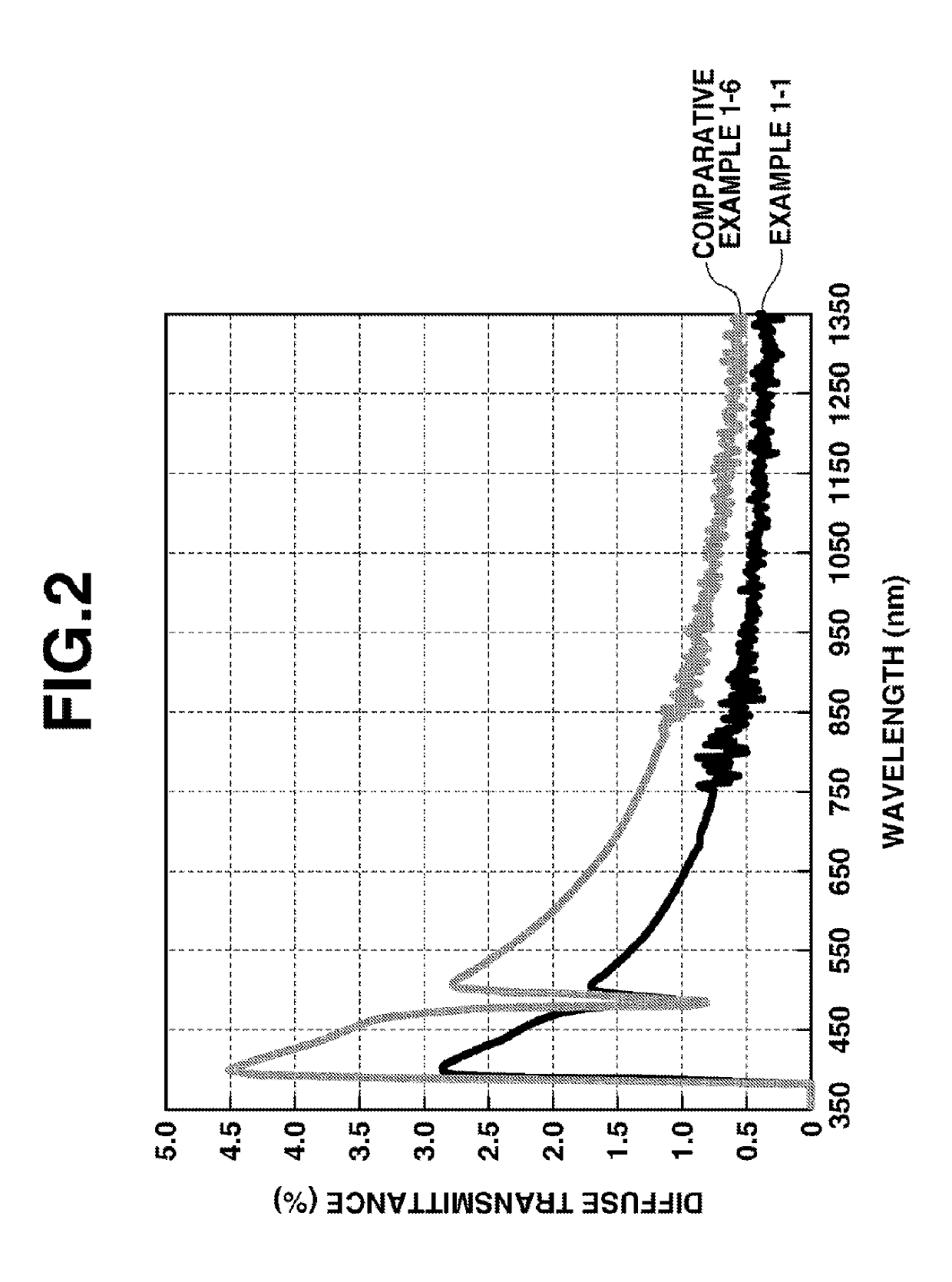
[0134]The results of Examples 1-1 to 1-10 and Comparative Examples 1-1 to 1-8 are tabulated in Tables 1 and 2. FIG. 2 is a diagram showing diffuse transmittance spectra of Example 1-1 and Comparative Example 1-6.

TABLE 1Example1-11-21-31-41-5RawTerbiumMolar ratio (%)5050505050materialoxideRare earthTypeY2O3Y2O3Y2O3Y2O3Y2O3oxideMolar ratio (%)5050505050SinteringTypeZrO2ZrO2ZrO2ZrO2ZrO2aidContent (wt %)0.50.50.50.50.5StepsSource powder preparation3-component co-precipitationSinteringSintering temp. T1,5001,5001,5001,5001,500(° C.)Tempe...

example 2

Examples 2-1 to 2-22

[0143]Secondary sintered body samples were manufactured under the same conditions as in Example 1-1 except that at least any one of the molar ratio of Tb / Y, the type and amount of sintering aid was changed. They were similarly evaluated.

[0144]The results are shown in Tables 3 and 4.

TABLE 3Example2-12-22-32-42-5Raw materialTerbiumMolar ratio (%)4040404050oxideRare earthTypeY2O3Y2O3Y2O3Y2O3Y2O3oxideMolar ratio (%)6060606050SinteringTypeZrO2ZrO2HfO2HfO2ZrO2aidContent (wt %)13131StepsSource powder preparation3-component co-precipitationSinteringSintering temp. T1,5001,6001,4001,5501,500(° C.)Temperature T1 (° C.)1,3001,3001,3001,3001,300Heatingup to T1100100100100100ratesubsequent2020202020(° C. / h)to T1Time (hr)22222AtmospherevacuumvacuumvacuumvacuumvacuumHIPTemperature (° C.)1,5001,6001,4001,5501,500Heating rate (° C. / h)300300300300300Time (hr)33333Pressure (MPa)198198198198198Evaluation resultsRelative density (%)96.895.496.696.196.2of primary sintered bodyAverage ...


PUM

PropertyMeasurementUnit
temperature T1aaaaaaaaaa
transmittanceaaaaaaaaaa

Abstract

A transparent ceramic material is manufactured by molding a source powder into a compact, the source powder comprising a rare earth oxide consisting of at least 40 mol % of terbium oxide and the balance of another rare earth oxide, and a sintering aid, sintering the compact at a temperature T (1,300° C.≤T≤1,650° C.) by heating from room temperature to T1 (1200° C.≤T1≤T) at a rate of at least 100° C./h, and optionally heating from T1 at a rate of 1-95° C./h, and HIP treating the sintered compact at 1,300-1,650° C. The ceramic material has improved diffuse transmittance in the visible region and functions as a magneto-optical part in a broad visible to NIR region.

Description

CROSS-REFERENCE TO RELATED APPLICATION[0001]This non-provisional application claims priority under 35 U.S.C. § 119(a) on Patent Application No. 2018-043076 filed in Japan on Mar. 9, 2018, the entire contents of which are hereby incorporated by reference.TECHNICAL FIELD[0002]This invention relates to a method for manufacturing a transparent ceramic material in the form of a Tb-based complex oxide sintered body having a high transparency or light transmittance in the visible to near-infrared (NIR) region, a transparent ceramic material manufactured thereby, and a magneto-optical device.BACKGROUND ART[0003]There have been developed and manufactured a wide variety of ceramics covering from traditional ceramics such as tiles and potteries to fine ceramics such as piezoelectric parts, superconductor parts and transparent ceramics.[0004]Transparent ceramics draw attention as a new replacement to single crystals since laser oscillation by ceramics was reported in 1990s. Transparent ceramics...

Claims


Application Information

Patent Timeline
Patent Type & Authority Applications(United States)
IPC IPC(8): C04B35/505C04B35/645G02F1/00
CPCC04B35/505G02F1/093C04B2235/6562C04B2235/9653G02F1/0036C04B2235/661C04B2235/3225C04B2235/602C04B35/6455C04B2235/3244C04B35/50C04B35/622G02F1/09C04B2235/3227C04B2235/785C04B2235/786C04B35/6264C04B35/6265C04B35/6268C04B35/62685C04B35/6303C04B35/64C04B35/645C04B2235/3205C04B2235/3206C04B2235/3208C04B2235/3213C04B2235/3215C04B2235/3224C04B2235/3232C04B2235/3852C04B2235/60C04B2235/604C04B2235/658C04B2235/6581C04B2235/6583C04B2235/662C04B2235/663C04B2235/664C04B2235/762G02B1/02C01F17/32
Inventor TANAKA, KEITAAOKI, SHINJIMAKIKAWA, SHINJI
Owner SHIN ETSU CHEM IND CO LTD
Why Eureka
Try Eureka