Object recognition device and vehicle travel control system

a technology of object recognition and control system, which is applied in the direction of scene recognition, image enhancement, instruments, etc., can solve the problems of false recognition of objects, unreasonably wide or narrow determination range from a viewpoint of true reliability, and deterioration of accuracy, so as to improve the accuracy of fusion processing and reduce the reliability of detected object position. , the effect of determining the rang

Active Publication Date: 2019-09-12
TOYOTA JIDOSHA KK
View PDF9 Cites 4 Cited by
  • Summary
  • Abstract
  • Description
  • Claims
  • Application Information

AI Technical Summary

Benefits of technology

[0030]Position reliability of the first object is higher as the first determination range is smaller.
[0031]Position reliability of the second object is higher as the second determination range is smaller.
[0032]The vehicle travel control device sets an upper limit of a control amount in the vehicle travel control higher as the position reliability is higher.
[0033]According to the present disclosure, the first determination range and the second determination range used in the fusion processing are respectively determined according to pixel densities of the first object and the second object. As the pixel density is lower, the determination range is set to be larger, because reliability of the detected object position is lower. That is to say, the first determination range and the second determination range are flexibly set according to the reliability of the detected object position. Therefore, the first determination range and the second determination range are prevented from being unreasonably wide or narrow. As a result, accuracy of the fusion processing increases and thus false recognition of objects is suppressed.

Problems solved by technology

Therefore, if the determination range used in the fusion processing is set to have a same size regardless of the camera type, the determination range may be unreasonably wide or narrow from a viewpoint of true reliability.
Setting such the inappropriate determination range deteriorates accuracy of the fusion processing and thus causes false recognition of objects.
As a result, accuracy of the fusion processing increases and thus false recognition of objects is suppressed.

Method used


Image

  • Object recognition device and vehicle travel control system
  • Object recognition device and vehicle travel control system
  • Object recognition device and vehicle travel control system

Examples


Embodiment Construction

[0047]Embodiments of the present disclosure will be described below with reference to the attached drawings.

1. Object Recognition Device

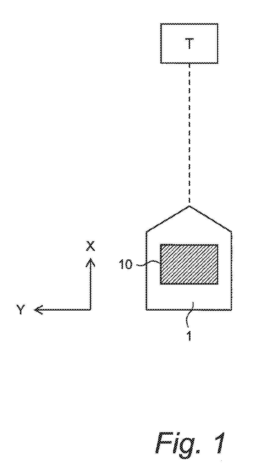
[0048]FIG. 1 is a conceptual diagram for explaining an object recognition device 10 according to an embodiment. The object recognition device 10 is installed on a vehicle 1 and executes “object recognition processing” that recognizes an object T around the vehicle 1. A result of the object recognition processing is used for driving support control, autonomous driving control, and the like. In the following description, an X-direction represents a longitudinal direction of the vehicle 1 and a Y-direction represents a lateral direction of the vehicle 1.

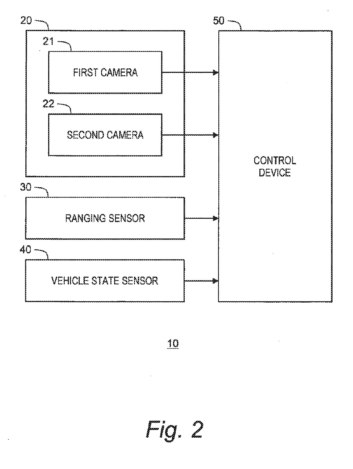
[0049]FIG. 2 is a block diagram showing a configuration example of the object recognition device 10 according to the present embodiment. The object recognition device 10 is provided with a camera device 20, a ranging sensor 30, a vehicle state sensor 40, and a control device (controller) 50.

[0050]The ca...


PUM


Abstract

An object recognition device installed on a vehicle includes a first camera detecting a first object, a second camera detecting a second object, a ranging sensor detecting a third object, and a controller. The controller sets first to third determination ranges with respect to detected positions of the first to third objects, respectively, and executes fusion processing by comparing the determination ranges. First and second pixel densities being pixel densities of the first and second objects are determined based on detected distances of the first and second objects, angles of view and numbers of pixels of the first and second cameras, respectively. The controller sets the first determination range larger as the first pixel density is lower, and sets the second determination range larger as the second pixel density is lower.

Description

BACKGROUNDTechnical Field[0001]The present disclosure relates to an object recognition device and a vehicle travel control system installed on a vehicle.Background Art[0002]Patent Literature 1 discloses an object detection device that detects an object by using a radar and a monocular camera. The object detected based on detection information by the radar is a first object. The object detected based on a captured image by the monocular camera is a second object. The object detection device determines whether or not the first object and the second object are close to each other. More specifically, the object detection device sets a first error region centered at a detected point of the first object and a second error region centered at a detected point of the second object. When the first error region and the second error region overlap with each other, the object detection device determines that the first object and the second object are close to each other. When the first object an...

Claims


Application Information

Patent Timeline
Patent Type & Authority Applications(United States)
IPC IPC(8): G06K9/00G06T7/70G05D1/02G01S17/93G01S13/931G01S17/86G01S17/931
CPCG06K9/00805G06T2207/30261G05D1/0246G01S17/936G06T7/70G08G1/165G08G1/166B60R21/01B60R2021/01027G01S13/867G01S13/58G01S17/58G01S17/06G01S13/931G01S2013/9318G01S2013/9319G01S2013/93185G01S2013/9323G01S2013/93271G01S2013/932G01S17/86G01S17/931G01S7/403G06V20/58
Inventor OZAWA, JUNNAGATA, SHINICHI
Owner TOYOTA JIDOSHA KK
Why Eureka
Try Eureka