Image Pickup apparatus and focus control method

a pickup apparatus and focus control technology, applied in the direction of camera focusing arrangement, printers, instruments, etc., can solve the problems of phase difference af becoming difficult to be carried out, focusing out of the allowable range of distance measurement, and affecting the accuracy of focusing control, so as to achieve high reliability and low reliability of focusing detection. the effect of in-focus position

Active Publication Date: 2010-06-17
SONY CORP
View PDF2 Cites 54 Cited by
  • Summary
  • Abstract
  • Description
  • Claims
  • Application Information

AI Technical Summary

Benefits of technology

[0011]According to any embodiment of the present invention, a first pixel group is provided for realizing a pupil-dividing function by receiving light fluxes from a subject passing through a pair of portion areas oppositely biased from each other in a predetermined direction on an exit pupil in the photographic optical system. In addition, a second pixel group without the pupil-dividing function is also provided. If it is determined that the pixel signal from the first pixel group satisfies a predetermined condition and the reliability of the detection of in-focus position is high, a focus lens is driven toward an in-focus position detected by focus detection of a phase-difference detection system based on a pixel signal of the first pixel group. On the other hand, if it is determined that the pixel signal from the first pixel group does not satisfy the predetermined condition and the reliability of the detection of in-focus position is low, the focus lens is driven in the direction of an in-focus position detected by making a comparison between the first information and the second information obtained as focus detection information used for focus detection with a contrast detection system on the basis of a pixel signal generated from the second pixel group when the focus lens is located on each of the first position and the second position. As a result, even when the phase difference AF is hardly operated by the imaging element with phase-difference detection function, a suitable focus control can be performed.

Problems solved by technology

However, the image pickup apparatus of the above patent document employs the imaging element with phase-difference detection function, allegedly having a comparatively small range of allowable distance measurement.
Therefore, if the amount of defocus is large when starting the AF operation (significantly blurred state), focusing is out of an allowable range of distance measurement and the phase difference AF becomes difficult to be carried out.
However, if the lens is driven in the opposite direction from the point of focus, a quick AF operation (focus control) will become difficult.

Method used


Image

  • Image Pickup apparatus and focus control method
  • Image Pickup apparatus and focus control method
  • Image Pickup apparatus and focus control method

Examples


modified embodiment

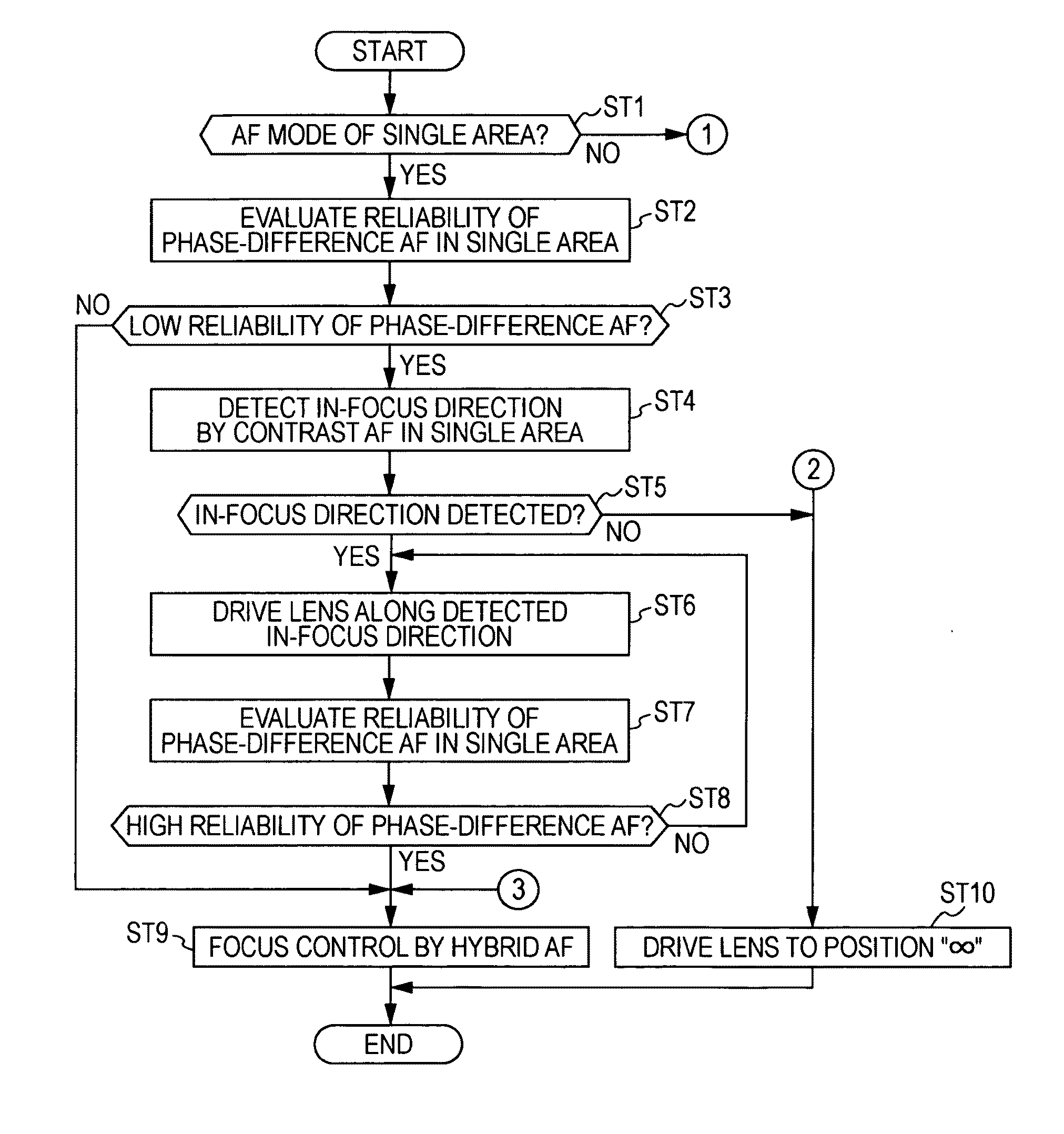
[0159]In the evaluation of the reliability of the phase difference AF in the above embodiment, the above Equation (2) may not be used as an evaluation function. Alternatively, any function that can determine whether the distance measurement with the AF line Lf is allowable may be used in stead of Equation (2).

[0160]In the imaging device of the above embodiment, as shown in FIG. 7, it is not necessary that 10 normal pixel lines Ln are placed between the AF lines Lf next to each other in the vertical direction. Alternatively, not more than nine normal pixel lines Ln or 11 or more normal pixel lines Ln may be sandwiched between the AF lines Lf.

[0161]The first AF pixel 11a and the second AF pixel 11b in the above embodiment may be provided with color filters, respectively. The color filter may lead to a decrease in sensitivity, while allowing a user to obtain photographic color pixel data.

[0162]In the case of the image pickup apparatus according to the above embodiment, the photographic...


PUM


Abstract

An image pickup apparatus includes an imaging element having a group of AF pixel pairs that realizes a pupil-dividing function and a group of normal pixels without such a pupil-dividing function. The image pickup apparatus performs focus control for driving a focus lens toward an in-focus position detected by phase different AF based on a pixel signal generated from the group of AF pixel pairs when it is determined that the reliability of the phase difference AF is high based on the pixel signal. The image pickup apparatus performs focus control for driving a focus lens in an in-focus direction detected by contrast AF based on a pixel signal generated from the group of normal pixels when it is determined that the reliability of the phase difference AF is low.

Description

CROSS-REFERENCE TO RELATED APPLICATION[0001]The present application claims priority from Japanese Patent Application No. JP 2008-318180 filed in the Japanese Patent Office on Dec. 15, 2008, the entire content of which is incorporated herein by reference.BACKGROUND OF THE INVENTION[0002]1. Field of the Invention[0003]The present invention relates to an image pickup apparatus having an imaging element with a first pixel group that realizes a pupil-dividing function.[0004]2. Description of the Related Art[0005]Some of imaging elements have specific pixels (pixels for phase difference AF) for performing autofocus control with a phase difference detection system (hereinafter, also referred to as a “phase difference AF”).[0006]For instance, Japanese Published Patent Application No. 2008-147821 discloses an image pickup apparatus provided with an imaging element having a plurality of pixel pairs for phase difference AF in which the centers of openings of the respective light-shielding plat...

Claims


Application Information

Patent Timeline
Patent Type & Authority Applications(United States)
IPC IPC(8): G03B13/00
CPCG03B13/00H04N23/672H04N23/673
Inventor ONO, RIICHIFUJII, SHINICHI
Owner SONY CORP
Why Eureka
Try Eureka