Toolbox

Active Publication Date: 2019-09-19
KO MING HONG
View PDF2 Cites 4 Cited by
  • Summary
  • Abstract
  • Description
  • Claims
  • Application Information

AI Technical Summary

Benefits of technology

[0010]Thereby, the toolbox contains the two covers, and each cover includes the shell, the frame, and the tool rack, wherein the shell has the bottom wall and the annular wall which are made of the plate in variou

Problems solved by technology

However, in producing toolboxes with injection molding, precise molds are necessary, causing increasing of production cost of the toolboxes.
Therefore, the manufacturers are forced to deal with increasing inventory p

Method used


Image

  • Toolbox
  • Toolbox
  • Toolbox

Examples


Example

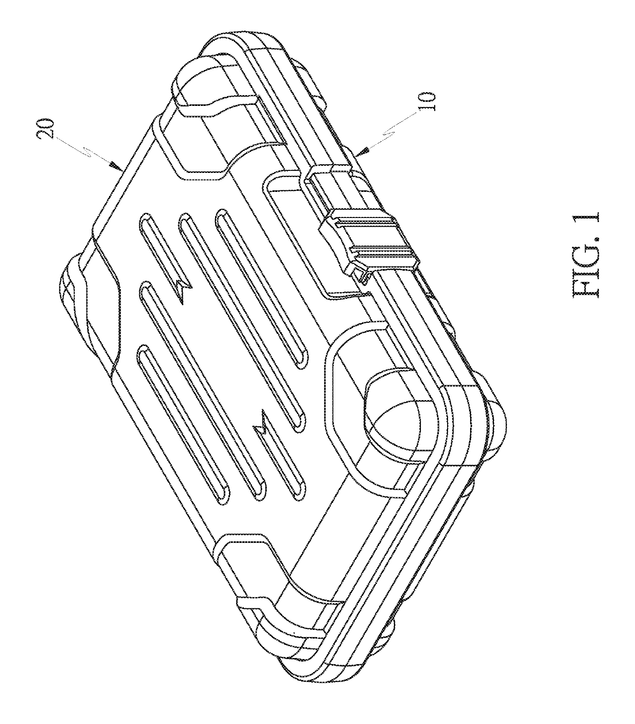
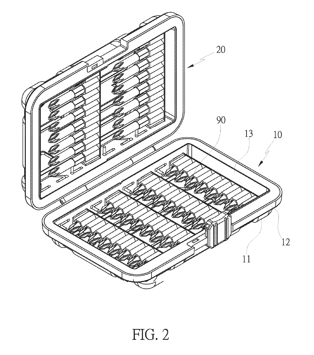
[0017]With reference to FIGS. 4-5, a toolbox according to a preferred embodiment of the present invention is employed to accommodate multiple tools 90 (such as wrench, sockets, or bits) and comprises: two covers 10, 20 which are rotatably connected with each other, as shown in FIGS. 1 and 2, wherein the two covers 10, 20 are rotated away from or close to each other so as to open or close the toolbox. Since one of the two covers 10 is identical to the other cover 20, further remarks of the other cover 20 are omitted.

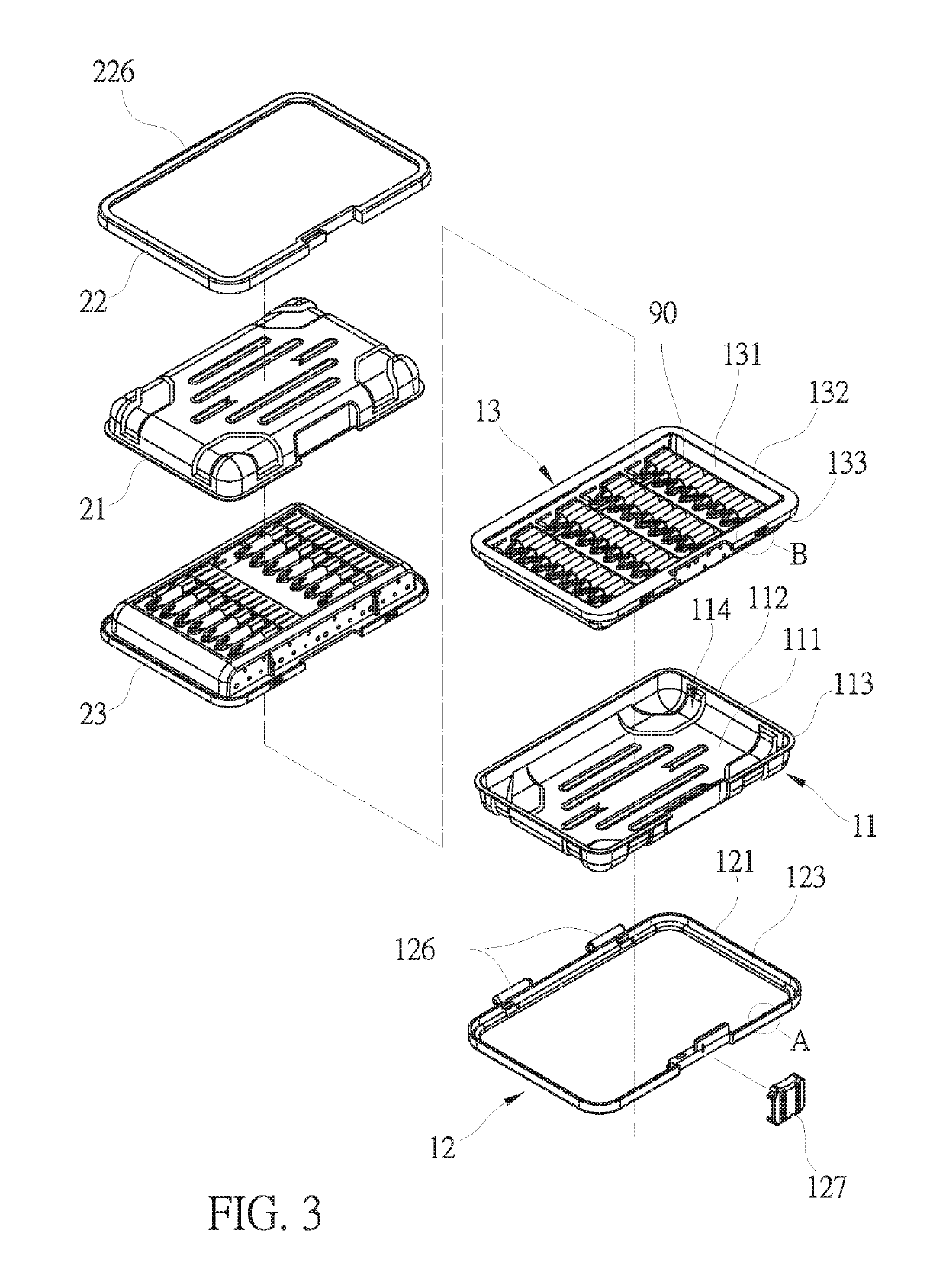
[0018]Referring to FIGS. 1-4, the one cover 10 includes a shell 11, a frame 12, and a tool rack 13.

[0019]The shell 11 is a thin-walled structure and includes a bottom wall 111, an annular wall 112, and a locking lip 113, wherein the annular wall 112 extending upward from and surrounding the bottom wall 111 so as to define a hollow receiving space 114 with the bottom wall 112. The hollow receiving space 114 faces the other cover 20. The locking lip 113 extends outward from...


PUM


Abstract

A toolbox contains two covers which are rotatably connected with each other and are rotated away from or close to each other so as to open or close the toolbox. At least one of the two covers includes a shell, a frame, and a tool rack. The shell includes a bottom wall and an annular wall, and the annular wall extends upward from and surrounds the bottom wall so as to define a hollow receiving space with the bottom wall. The frame surrounds the annular wall and connect with the tool rack so that the shell is engaged between frame and tool rack.

Description

FIELD OF THE INVENTION[0001]The present invention relates to a toolbox.BACKGROUND OF THE INVENTION[0002]A conventional toolbox is applied to accommodate multiple tools. Preferably, the toolbox and the multiple tools are packed together for sale.[0003]The toolbox is made of plastic or rubber in injection molding manner so as to obtain exact structure and appearance and silky touch. Preferably, the toolbox is made in multi-shot sequential injection molding or bi-injection molding so as to achieve multiple hardness and colors.[0004]However, in producing toolboxes with injection molding, precise molds are necessary, causing increasing of production cost of the toolboxes. To scatter the cost of the molds, the toolboxes have to be produced in mass production. Therefore, the manufacturers are forced to deal with increasing inventory pressure. Affordable variations of models of the toolboxes are limited. When a new model is published on the market, manufacturers and retailers are unable to ...

Claims


Application Information

Patent Timeline
IPC IPC(8): B25H3/02B25H3/00
CPCB25H3/025B25H3/04B25H3/003B25H3/06
Inventor KO, MING-HONG
Owner KO MING HONG
Why Eureka
Try Eureka