Device for dismountably connecting two intersecting formwork beams

a technology of formwork beams and beams, which is applied in the direction of forms/shuttering/falseworks, shaping building parts, constructions, etc., can solve the problems of shortening the service life of the beams, requiring considerable manpower, and difficult to quantify the strength of the joint, so as to achieve constant and readily controlled clamping pressure, easy to apply, and low dependence on human action for mounting

Active Publication Date: 2019-09-19
SISTEMAS TCNICOS DE ENCOFRADOS
View PDF10 Cites 1 Cited by
  • Summary
  • Abstract
  • Description
  • Claims
  • Application Information

AI Technical Summary

Benefits of technology

[0008]To overcome the drawbacks mentioned and to produce devices, for connecting wooden, metal or combined I-beams, having properties of being easy to apply, having constant and readily controlled clamping pressures, having little dependency on human action for mounting, the inventor has, after much research and testing, successfully produced a new device for connecting intersecting formwork beams which has the above-mentioned features together with that of easy recovery from one building site to another, by being easily dismounted without impairing its structural and functional properties.
[0015]The material of the steel device can be a steel having high resilience properties, optionally heat-treated, so that once it is applied between the two beams that are to be connected, the pressure exerted on the joint is constant, ensuring that the two beams are connected and preventing the upper beam from tipping, especially when workers move overhead while mounting the formwork boards.

Problems solved by technology

This is a laborious, though effective system which, apart from its simplicity and adaptability, has many drawbacks, such as a shortening of the service life of the beams through the deterioration that is caused by the action of the nails, by disassembly and removal of the nails, which require considerable manpower, and by the fact that it is difficult to quantify the strength of the joint, since this depends on many variable factors, such as the diameter of the nail, the angle and depth of nailing, the state of the wood etc.

Method used


Image

  • Device for dismountably connecting two intersecting formwork beams
  • Device for dismountably connecting two intersecting formwork beams
  • Device for dismountably connecting two intersecting formwork beams

Examples


Embodiment Construction

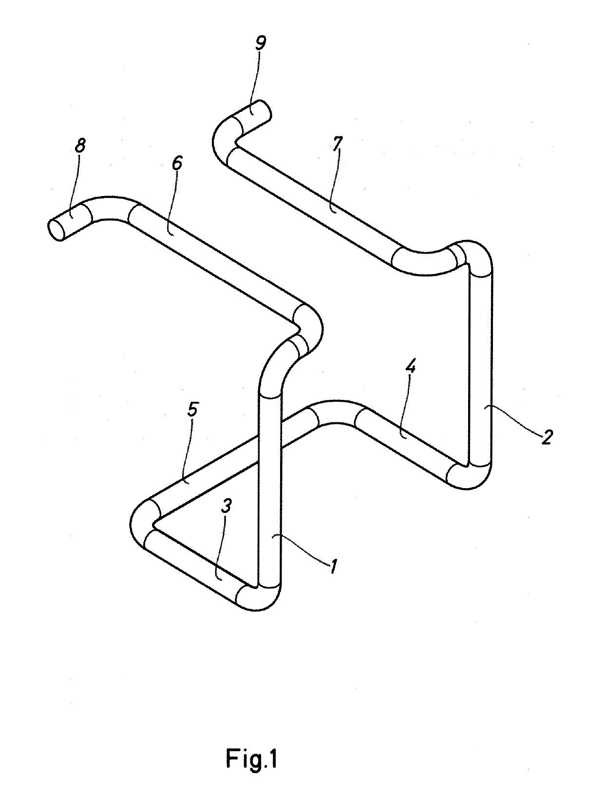
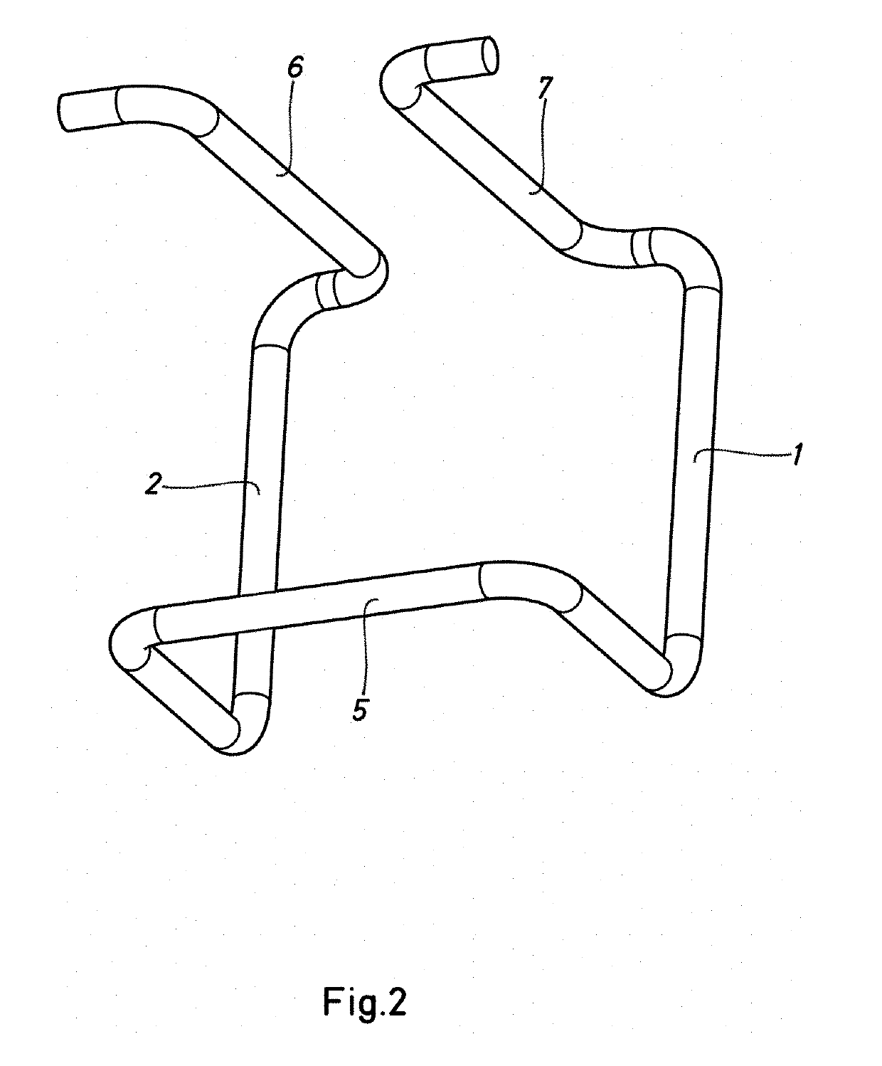
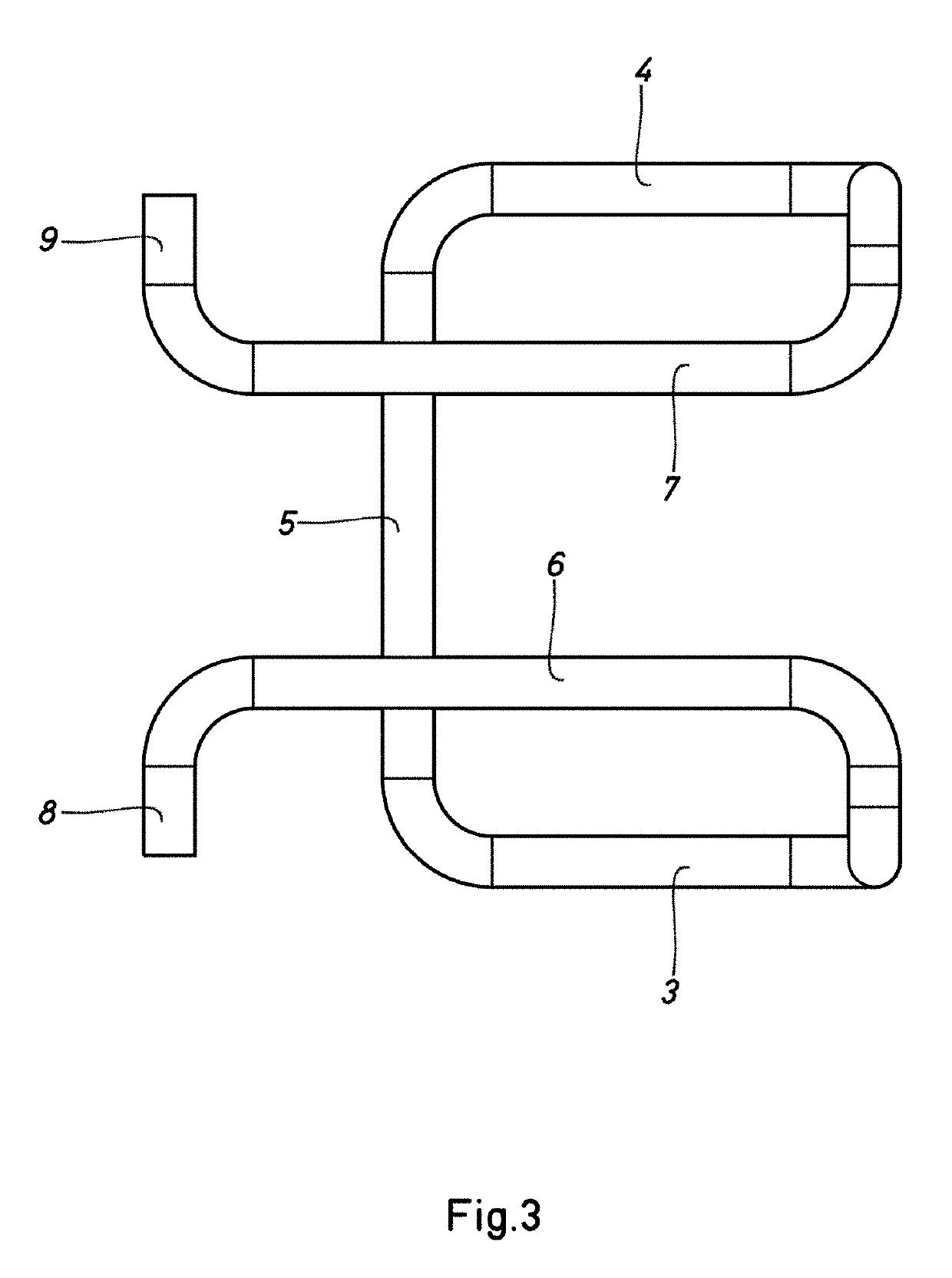
[0063]As can be seen in FIGS. 1 to 3, the device for dismountably connecting intersecting formwork beams, according to the present invention, comprises two arms that diverge slightly upwards -1- and -2-, and are joined to respective, substantially horizontal sections -3- and -4-, which together with a crosspiece -5- form a U- or V-shaped bridge. At the top, the arms -1- and -2- extend into respective straight, substantially horizontal extensions -6- and -7-. The various components mentioned, together forming in succession the connection device based on a resilient steel rod, are joined by means of multiple curved elbows, which have not been specifically numbered for greater clarity of the figures. The straight extensions of the upper portion -6- and -7- end in respective folded regions -8- and -9- positioned in the same plane as determined by the extensions -6- and -7-.

[0064]FIGS. 4 and 5 are a perspective view and a side elevation view, respectively, of a version of the device of t...


PUM


Abstract

The invention relates to a device for dismountably connecting two intersecting formwork beams, which comprises a single-component elastic structure with two arms joining together respective areas for pressing the two beams together in support areas, and which can longitudinally slide over one of the beams until it reaches the other beam, the device being elastically deformed by means of pressure or impact thereon, so as to clamp or hold both beams and press them together.

Description

CROSS-REFERENCE TO RELATED APPLICATIONS[0001]This application is a divisional of U.S. application Ser. No. 15 / 576,603, filed on Nov. 22, 2017 as the U.S. National Phase under 35. U.S.C. § 371 of International Application PCT / ES2016 / 070399, filed May 26, 2016, which claims priority to Spanish Patent Application No. P 201530733, filed May 27, 2015. The disclosures of the above-described applications are hereby incorporated by reference in their entirety.FIELD OF THE INVENTION[0002]The present patent for an invention relates to a device for dismountably connecting two intersecting formwork beams, conferring appreciable features of novelty and inventive step.[0003]The formwork beams will be wooden, metal or combined I-beams, i.e., in the case of combined, they will be formed by a metal portion and a wooden portion.BACKGROUND OF THE INVENTION[0004]Wooden I-beams are widely used in the construction industry in most industrially advanced countries and are intended particularly for supporti...

Claims


Application Information

Patent Timeline
Patent Type & Authority Applications(United States)
IPC IPC(8): E04G11/50F16B7/04F16B2/24E04B1/24E04G17/02E04G17/04
CPCF16B2/24E04B1/2403F16B7/04F16B7/0493E04B2001/2424E04G11/50E04G17/02E04G17/04F16B2/248F16B2/245F16B2/22
Inventor UBIÑANA FELIX, JOSE LUIS
Owner SISTEMAS TCNICOS DE ENCOFRADOS
Why Eureka
Try Eureka