Ball socket for a ball joint

Active Publication Date: 2019-09-19
ZF FRIEDRICHSHAFEN AG
View PDF0 Cites 1 Cited by
  • Summary
  • Abstract
  • Description
  • Claims
  • Application Information

AI Technical Summary

Benefits of technology

[0024]In one embodiment the slot is of stepped form in the, or in a radial direction relative to the mid-point of the spherical surface and/or in the, or in a direction transverse to the longitudinal axis. In that case the slot is formed in the injection-molding die in particular by two projections of the injection-molding die arranged opposite but offset from one another. Thus the projections can be made shorter, which reduces the risk of wearing down the projection. For example, the length of the projections corresponds in each case to half the slot depth

Problems solved by technology

In the course of wear tests, however, it has been found that under high loads, for example at surface pressures in excess of 130 MPa, the material of the ball socket f

Method used


Image

  • Ball socket for a ball joint
  • Ball socket for a ball joint
  • Ball socket for a ball joint

Examples


Embodiment Construction

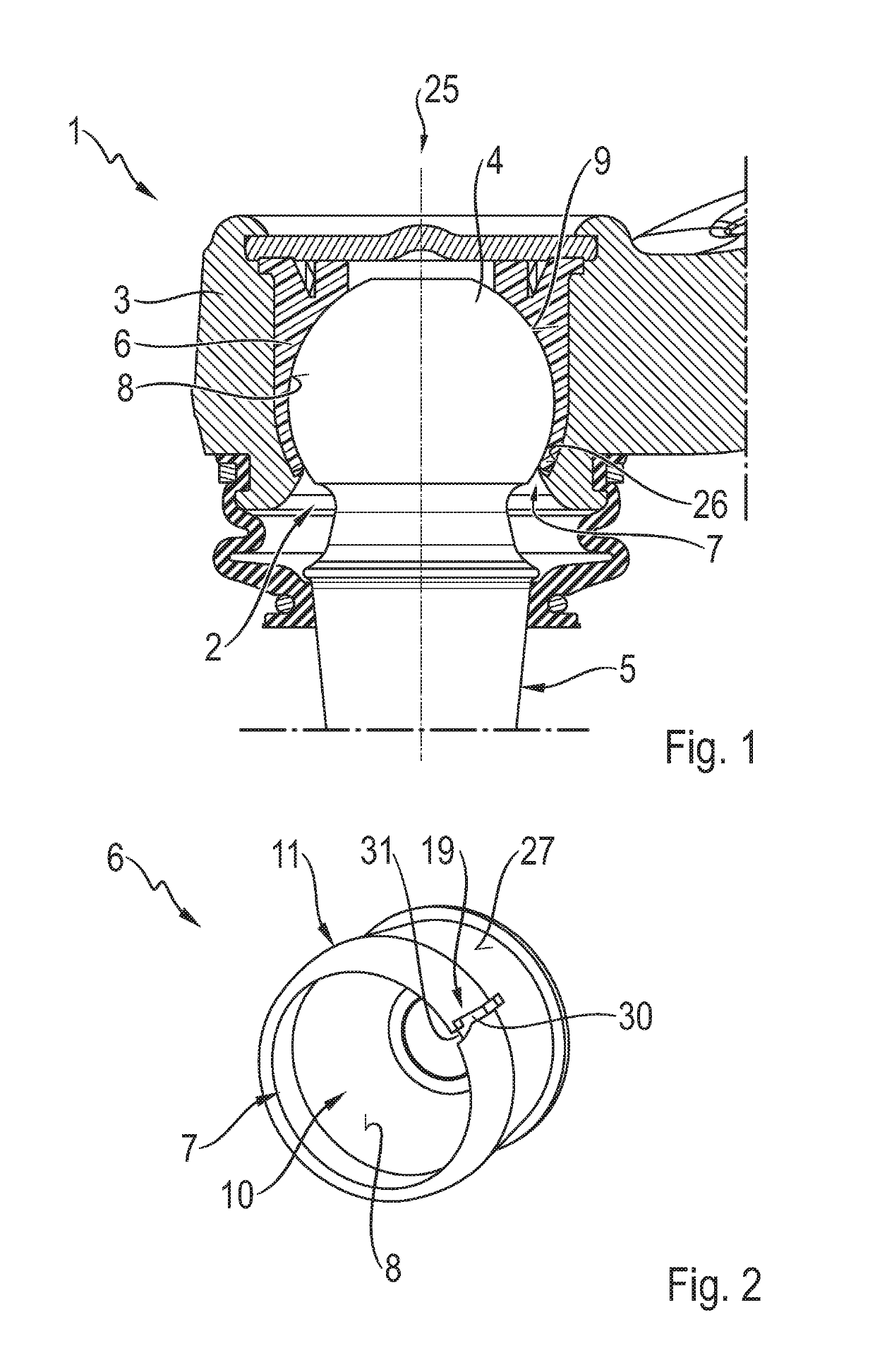
[0039]FIG. 1 shows a sectioned view of a ball joint 1, which comprises a joint housing 3 with a housing opening 2 and a ball stud 5 with a joint ball 4, which with its joint ball is fitted into the joint housing 3 with a ball socket 6 interposed and which extends out of the housing through the housing opening 2. The joint ball 4 sits inside the ball socket 6, which has a ball socket opening 7 through which the ball stud 5 extends out of the ball socket 6. Furthermore, the ball socket 6 has an inside peripheral surface 8 against which the joint ball 4 rests and can move by sliding. In the assembled condition of the ball socket 6 shown in FIG. 1 the inside peripheral surface 8 as a whole lies on a spherical surface 9, which in the fitted condition of the ball joint 1 coincides with the surface of the joint ball 4.

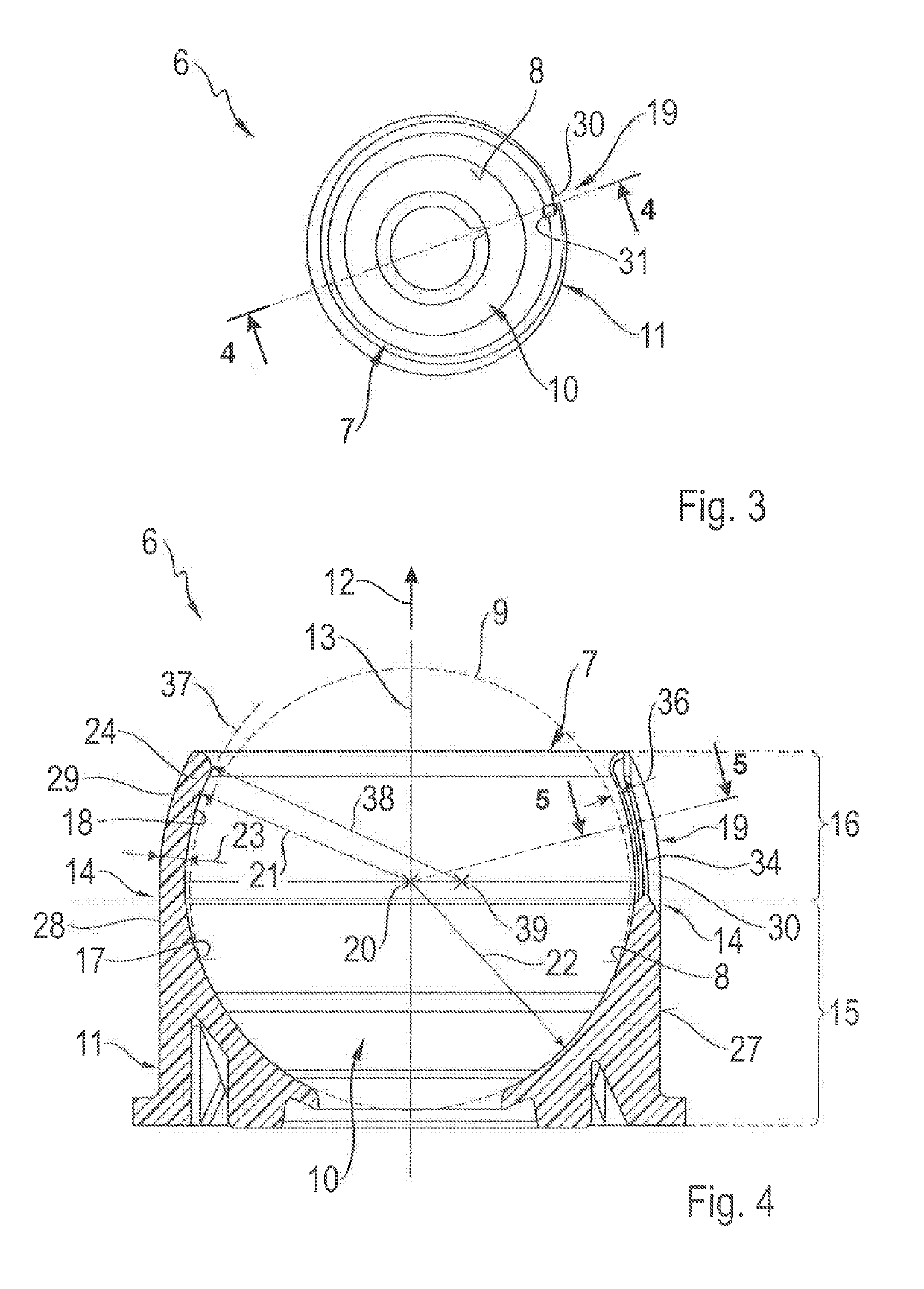
[0040]FIG. 2 shows a perspective representation of the ball socket 6 before it is fitted into the joint housing 3, whereas FIG. 3 shows a view of the ball socket 6 from above...


PUM

PropertyMeasurementUnit
Thicknessaaaaaaaaaa
Lengthaaaaaaaaaa
Widthaaaaaaaaaa

Abstract

A socket for a ball joint having a socket body with an opening and a hollow space, which comprises a concave inside peripheral surface that delimits the hollow space and extends around a longitudinal axis, and which is axially divided into two body halves which merge together in a transition zone, each of which comprises an inside peripheral surface half. A first body half comprises a first inside peripheral surface half which lies on a spherical surface and is closed, in the circumferential direction, and a second body half which comprises the socket opening, at least one slot extending axially and a second inside peripheral surface half which is closed in the circumferential direction, or closed apart from the slot. The second body half is designed such that the second inside peripheral surface half lies outside the spherical surface at least an axial distance away from the transition zone.

Description

[0001]This application is a National Stage completion of PCT / EP2017 / 077078 filed Oct. 24, 2017, which claims priority from German patent application serial no. 10 2016 224 045.5 filed Dec. 2, 2016.FIELD OF THE INVENTION[0002]The invention relates to a ball socket for a ball joint, having a ball socket body comprising a ball socket opening and a hollow space, which has a concave inside peripheral surface that delimits the hollow space and extends around a longitudinal axis orientated in an axial direction, and is divided along the longitudinal axis into two ball socket body halves arranged one behind the other, which merge into one another in a transition zone, each of which has an inside peripheral surface half of the inside peripheral surface that extends around the longitudinal axis, wherein a first one of the ball socket body halves contains a first one of the inside peripheral surface halves, which lies on a spherical surface and is closed in the circumferential direction, and a...

Claims


Application Information

Patent Timeline
IPC IPC(8): F16C11/06
CPCF16C2220/04F16C11/0638F16C2240/60F16C2240/40F16C2240/70
Inventor RICHTER, THOMASPRINS, HANS
Owner ZF FRIEDRICHSHAFEN AG
Why Eureka
Try Eureka