Capacitive electromagnetic flowmeter
- Summary
- Abstract
- Description
- Claims
- Application Information
AI Technical Summary
Benefits of technology
Problems solved by technology
Method used
Image
Examples
first embodiment
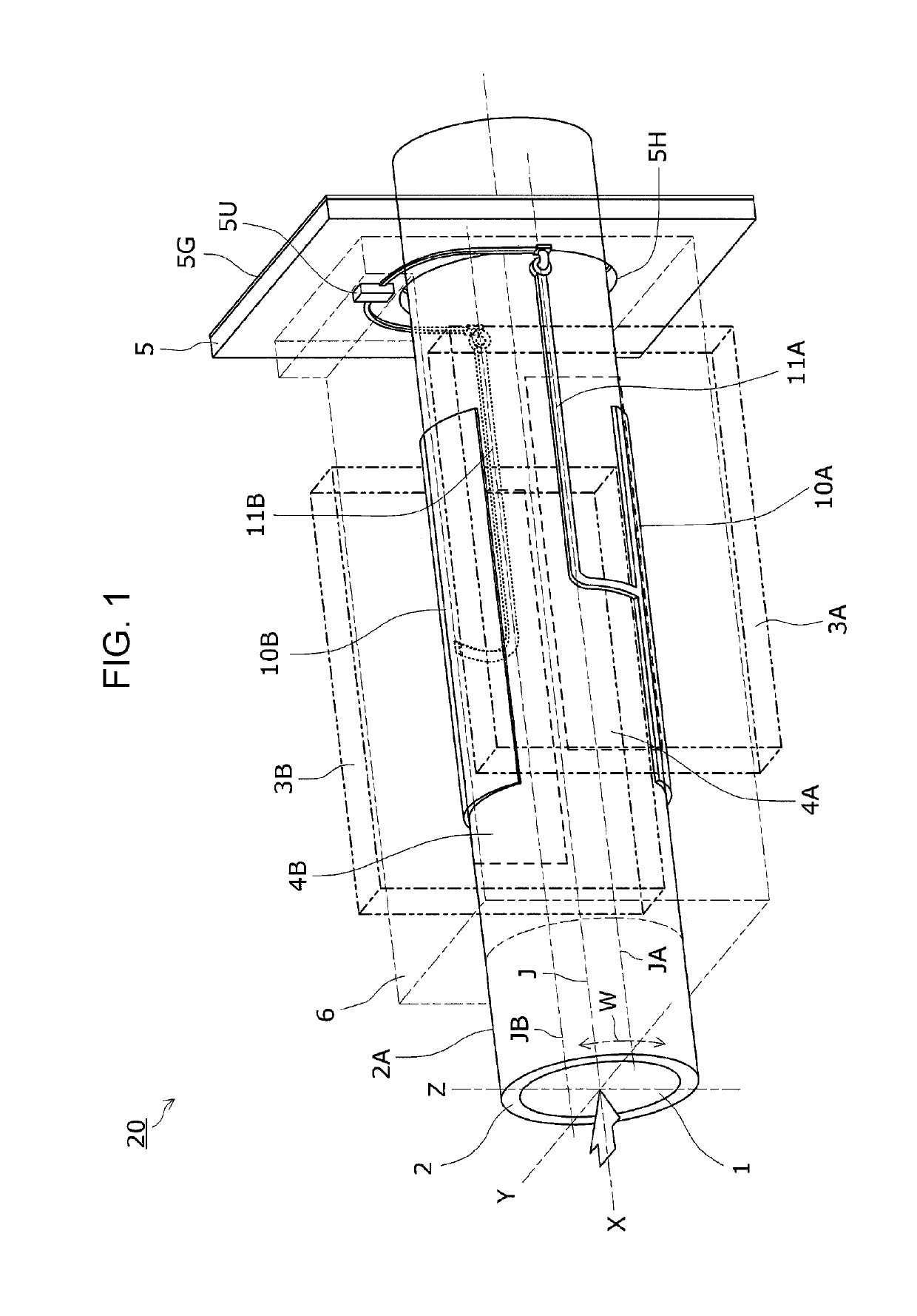
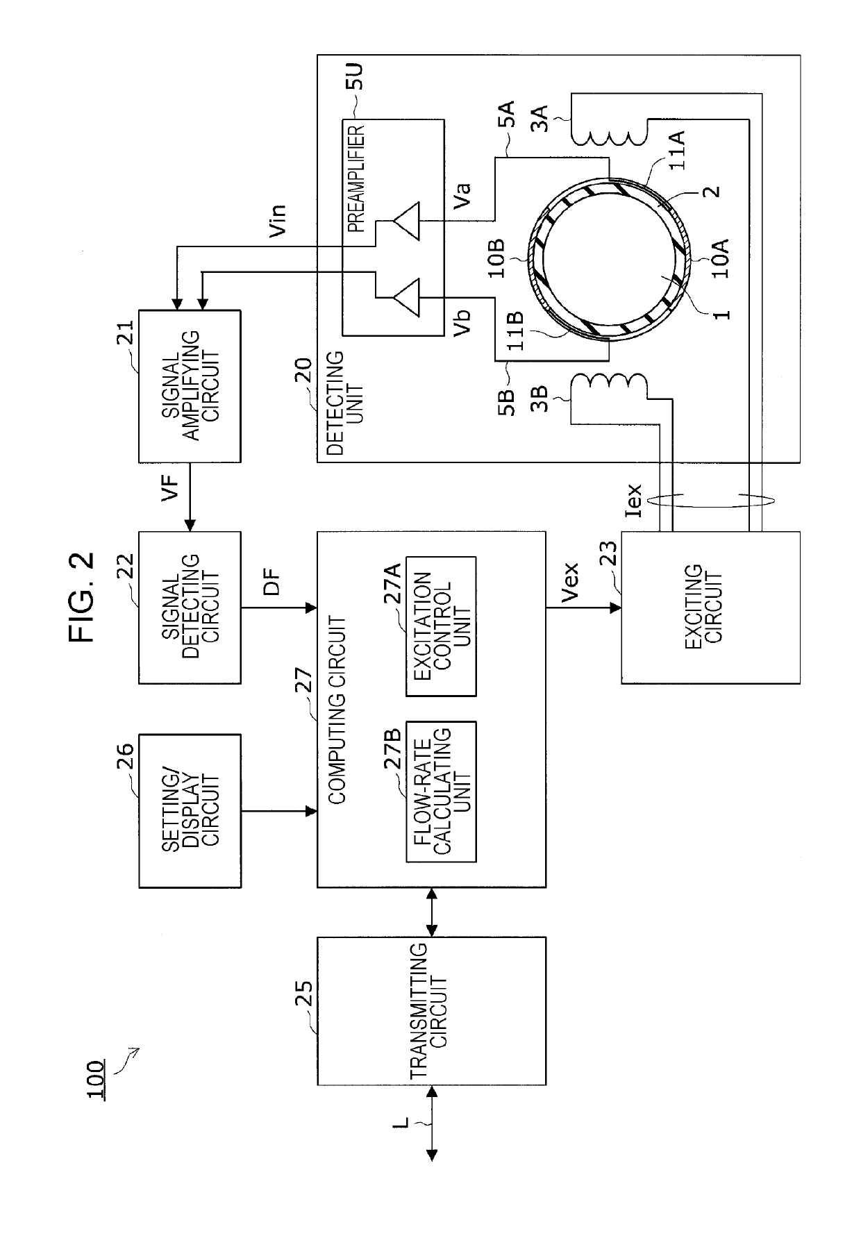
[0040]First, with reference to FIGS. 1 and 2, a capacitive electromagnetic flowmeter 100 according to a first embodiment of the present disclosure will be described. FIG. 1 is a perspective view illustrating a detecting unit of a capacitive electromagnetic flowmeter according to the first embodiment. FIG. 2 is a block diagram illustrating a circuit configuration of the capacitive electromagnetic flowmeter according to the first embodiment.
(Capacitive Electromagnetic Flowmeter)
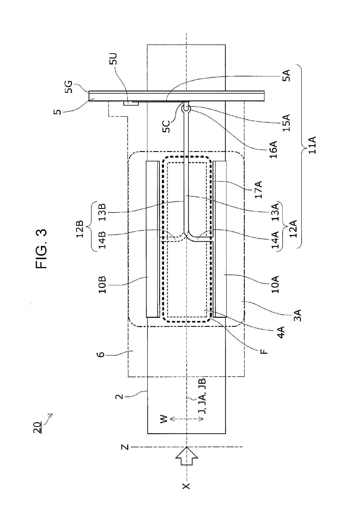
[0041]In the capacitive electromagnetic flowmeter 100, a magnetic flux applied by an exciting coil produces electromotive force in a fluid (object to be measured) flowing in a measuring tube, and electrodes on the outer periphery of the measuring tube detect the electromotive force using capacitance between the fluid and the electrodes. The detected electromotive force is then amplified, sampled, and subjected to signal processing. With this configuration, the capacitive electromagnetic flowmeter 100 measures t...
second embodiment
[0082]A capacitive electromagnetic flowmeter according to a second embodiment of the present disclosure will now be described with reference to FIGS. 7 and 8. FIG. 7 is a top view of a detecting unit according to the second embodiment. FIG. 8 is a side view of the detecting unit according to the second embodiment.
[0083]In the first embodiment, the circumferential wiring pattern 14A is connected at one end thereof to the center of the first edge 17A of the surface electrode 10A, and the circumferential wiring pattern 14B is connected at one end thereof to the center of the second edge 17B of the surface electrode 10B. However, the positions of connection are not limited to the centers of the first and second edges 17A and 17B.
[0084]In the present embodiment, the circumferential wiring patterns 14A and 14B are connected at respective ends thereof to respective edges of the surface electrodes 10A and 10B at positions symmetric with respect the tube axis J of the measuring tube 2.
[0085]...
third embodiment
[0088]A capacitive electromagnetic flowmeter according to a third embodiment of the present disclosure will now be described with reference to FIGS. 9 and 10. FIG. 9 is a top view of a detecting unit according to the third embodiment. FIG. 10 is a side view of the detecting unit according to the third embodiment.
[0089]In the first and second embodiments, the tube-side wiring pattern 12A includes the longitudinal wiring pattern 13A and the circumferential wiring pattern 14A, and the tube-side wiring pattern 12B includes the longitudinal wiring pattern 13B and the circumferential wiring pattern 14B. In the present embodiment, the tube-side wiring patterns 12A and 12B include only the longitudinal wiring patterns 13A and 13B, respectively.
[0090]In the present embodiment, as illustrated in FIGS. 9 and 10, the longitudinal wiring pattern 13A is connected at one end thereof to a third edge 17C of the surface electrode 10A extending along the circumferential direction W of the measuring tu...
PUM
 Abstract
Description
Claims
Application Information
 - R&D
- Intellectual Property
- Life Sciences
- Materials
- Tech Scout
- Unparalleled Data Quality
- Higher Quality Content
- 60% Fewer Hallucinations
Browse by: Latest US Patents, China's latest patents, Technical Efficacy Thesaurus, Application Domain, Technology Topic, Popular Technical Reports.
© 2025 PatSnap. All rights reserved.Legal|Privacy policy|Modern Slavery Act Transparency Statement|Sitemap|About US| Contact US: help@patsnap.com


