
Wire harness

Active Publication Date: 2017-08-31
YAZAKI CORP +1
View PDF4 Cites 4 Cited by
  • Summary
  • Abstract
  • Description
  • Claims
  • Application Information

AI Technical Summary

Benefits of technology

The present invention provides a wire harness that improves workability and reduces cost while preventing overcurrent flow. The wire harness has a structure with a conductive path as a main line, a branch line connected to the middle of the conductive path, and an overcurrent cut-off portion in the middle of the branch line. The connection between the conductive path and the branch line as well as the overcurrent cut-off portion are insulated and waterproofed. The wire harness can be easily wired and fixed to a wiring destination through a protector. The technical effects of the invention include improved workability, reduced cost, and prevention of overcurrent flow.

Problems solved by technology

Thus, there is a problem that working may be complicated.
In addition, the conductive path cannot be always extended from the harness terminal to the new device at the shortest distance.
Thus, there is another problem that the length of the conductive path turning back is increased accordingly, to thereby increase the cost.
Further, there is another problem that when there is necessity to prevent an overcurrent from flowing into the new device, the structure of the background-art wire harness cannot satisfy the necessity.

Method used


Image

  • Wire harness
  • Wire harness
  • Wire harness

Examples


embodiment

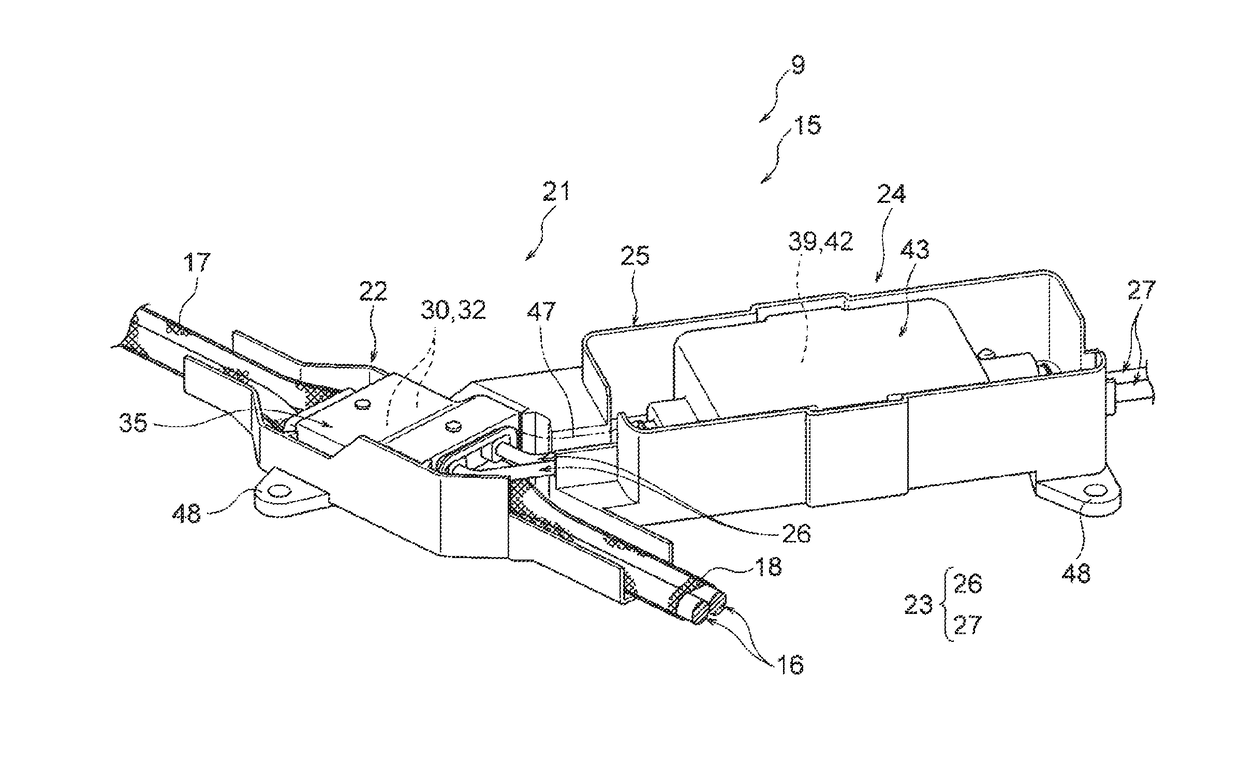
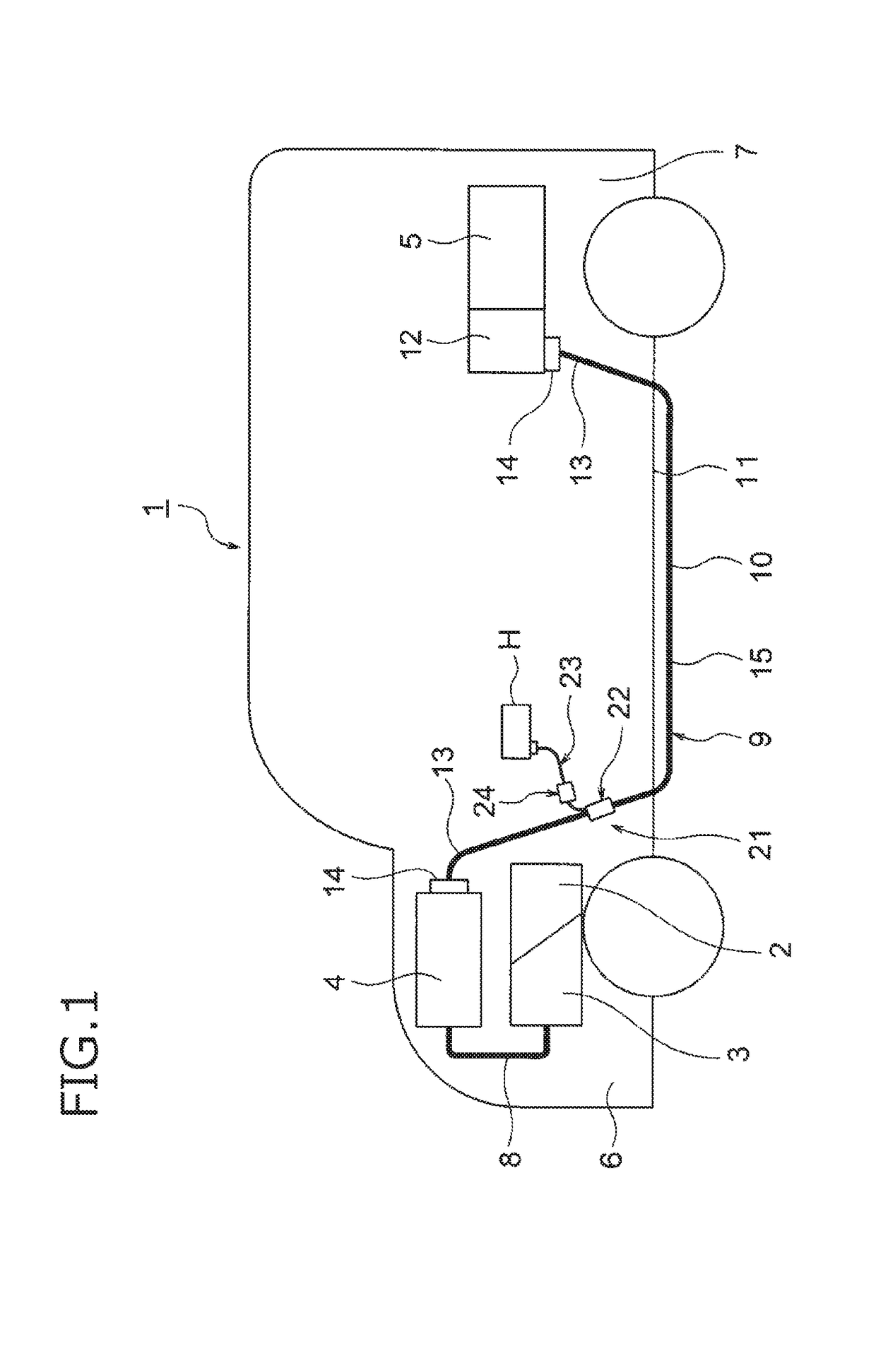
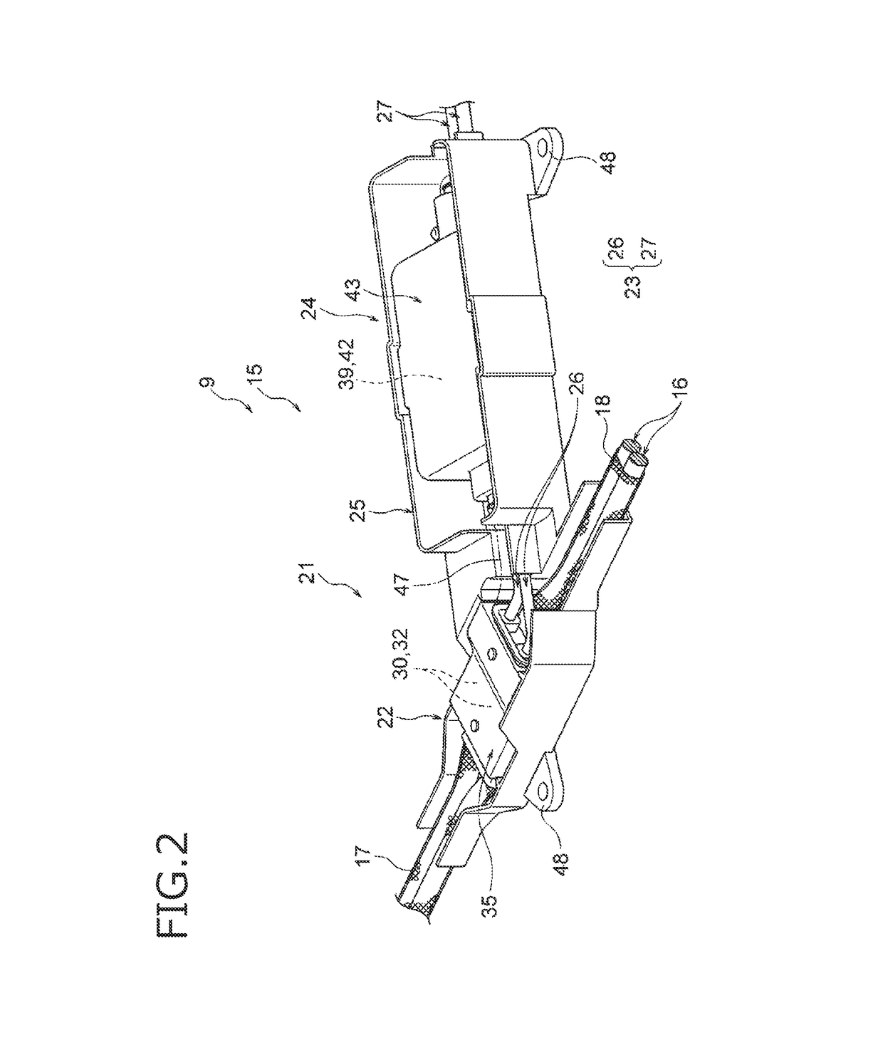
[0032]An embodiment will be described below with reference to the drawings. FIG. 1 is a schematic view showing a state in which a wire harness according to the invention is wired. FIG. 2 is a perspective view showing a branching structure portion in FIG. 1. FIG. 3 is a plan view showing the branching structure portion in FIG. 1.

[0033]In the present embodiment, the invention is applied to a wire harness to be wired in a hybrid car (which may be replaced by an electric car or the like).

1>

[0034]In FIG. 1, the reference numeral 1 represents a hybrid car. The hybrid car 1 is a vehicle driven by a mixture of two power sources, that is, an engine 2 and a motor unit 3. To the motor unit 3, electric power is supplied from a battery 5 (or a battery pack) through an inverter unit 4. In the embodiment, the engine 2, the motor unit 3 and the inverter unit 4 are mounted in an engine room 6 where there are front wheels etc. On the other hand, the battery 5 is mounted in a car rear portion 7 where ...


PUM


Abstract

A wire harness includes a conductive path configured to electrically connect between high-voltage devices. The conductive path includes a main line and a branch line that branches from the main line. An overcurrent cut-off portion is disposed on a way of the branch line to cut off an overcurrent.

Description

CROSS REFERENCE TO RELATED APPLICATIONS[0001]This application is based on Japanese Patent Application (No. 2016-033981) filed on Feb. 25, 2016, the contents of which are incorporated herein by reference.BACKGROUND OF THE INVENTION[0002]1. Field of the Invention[0003]The present invention relates to a wire harness provided with a conductive path to establish electric connection between high-voltage devices.[0004]2. Description of the Related Art[0005]For example, a wire harness disclosed in JP-A-2014-42443 has been known as a background-art wire harness for establishing electric connection between high-voltage devices (accessories) mounted on a hybrid car or an electric car. The wire harness has a configuration including one or plural conductive paths, a packing member for receiving and protecting the conductive paths, an external connection unit disposed at a harness terminal to establish connection with an external high-voltage device, and plural fixation members for fixedly attach...

Claims


Application Information

Patent Timeline
IPC IPC(8): B60R16/02H01B7/282H02H7/26H01R4/70
CPCB60R16/0215H02H7/26H01B7/282H01R4/70H02G1/145H02G3/0468H02G3/32H01R4/20H01R13/5208H01R31/02H01R2201/26H02H3/087
Inventor OGUE, TAKESHIKUBOSHIMA, HIDEHIKOHIRONAKA, RYOUJI
Owner YAZAKI CORP
Learn More