
Thin film balun

Active Publication Date: 2009-09-24
TDK CORPARATION
View PDF8 Cites 4 Cited by
  • Summary
  • Abstract
  • Description
  • Claims
  • Application Information

AI Technical Summary

Benefits of technology

[0010]With this structure, some points are still not clear with respect to details of operation mechanism by which thin film balun characteristics are improved which include transmission characteristics at the intended frequency and signal balancing (phase and amplitude). However, it is estimated that, since the capacitor is disposed to have a region which does not overlap a part of the coil opening, the effects on magnetic coupling of the unbalanced transmission line and balanced transmission line are reduced, compared to when the capacitor is disposed to overlap the whole coil opening, so that the characteristics of the thin film balun are improved. Here, the overlapping of the capacitor with the coil section and coil opening refers to an overlapping observed as seen from a facing direction of the first coil section and second coil section.
[0011]Preferably the capacitor is disposed not to overlap the whole area of the pair of coil openings. Accordingly, it is estimated that, since the magnetic flux passing through the coil opening is not blocked by the capacitor, the effects of the capacitor on the magnetic field are significantly reduced.
[0013]For example, the first coil section and the second coil section each have a corner, and the capacitor is disposed to overlap a part of a region above the corner. When the capacitor is disposed in a region which overlaps the coil-shaped balanced transmission line, also, it is estimated that satisfactory characteristics of thin film balun are provided. In addition, when the capacitor is disposed to overlap at least a part of the corner, wiring is made easier.
[0014]For example, the pair of first coil sections are disposed adjacent to each other on the same plane, and the pair of second coil sections are disposed to face the pair of first coil sections, and a pair of coil openings disposed adjacent to each other on a plane are defined by the first coil section and the second coil section. In this case, a region overlapping one coil opening of the pair of coil openings has the same area as a region overlapping the other coil opening of the pair of coil openings. In this way, when the coil openings are disposed adjacent to each other on the plane, it is estimated that, when the areas of the regions overlapping the two coil openings is equalized, the effects on the magnetic field of the two coil-shaped balanced transmission lines are made uniform as compared to when the capacitor overlaps only one coil opening. As a result, the balancing of two balanced signals outputted from the two coil-shaped balanced transmission lines increases.
[0015]More preferably, the capacitor is disposed so that the region overlapping one coil opening and the region overlapping the other coil opening are symmetrical with respect to a virtual line which divides the pair of coil openings into the two coil openings. In this way, when the capacitor is disposed so that the regions overlapping the two coil openings are symmetrical, it is estimated that the effects on the magnetic field of the two coil-shaped balanced transmission lines are made uniform as compared to when the regions are simply equalized.
[0016]According to the present invention, since the capacitor is disposed so that at least a part of the coil opening is exposed, thin film balun characteristics are improved which include transmission characteristics at the intended frequency and signal balancing (phase and amplitude).

Problems solved by technology

However, it became clear that, as long as the structure of the related art laminated balun is used, various characteristics required by thin film baluns cannot be further improved to a satisfactory level.

Method used


Image

  • Thin film balun
  • Thin film balun
  • Thin film balun

Examples


examples of embodiments

[0058]From a viewpoint of overlapping the coil openings C1 and C2, Examples 1 to 4 in which the arrangement of the capacitor 4 is changed, and Comparative example 1 was prepared. FIGS. 10 to 12 are a plan view illustrating the lower electrode of the capacitor of the thin film balun 1 in examples 2 to 4; and FIG. 13 is a plan view illustrating the lower electrode of the capacitor of the thin film balun 1 in the comparative example. Here, the arrangement regions of the lower electrode illustrated in FIGS. 10 to 13 correspond to the arrangement region of the upper electrode disposed to face the lower electrode, and further to the arrangement region of the capacitor. The capacitor arrangement according to the above examples and the comparative example will be described below.

example 1

[0059]In the thin film balun 1 of Example 1, as illustrated in FIG. 9, a reverse L-shaped lower electrode 33 of the capacitor 4 is disposed in the region Ar overlapping the coils 11 and 12 of the unbalanced transmission line 2.

example 2

[0060]In the thin film balun 1 of Example 2, as illustrated in FIG. 10, a lower electrode 34 of the capacitor 4 is disposed so that the capacitor 4 overlaps only one coil opening C2 by ¼ the area of that coil opening.


PUM


Abstract

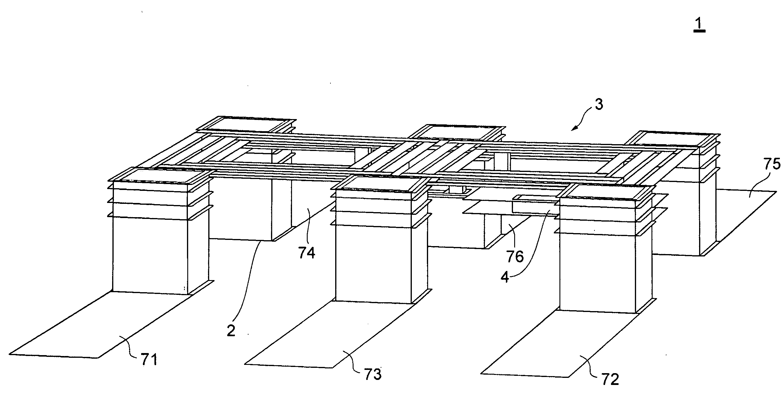
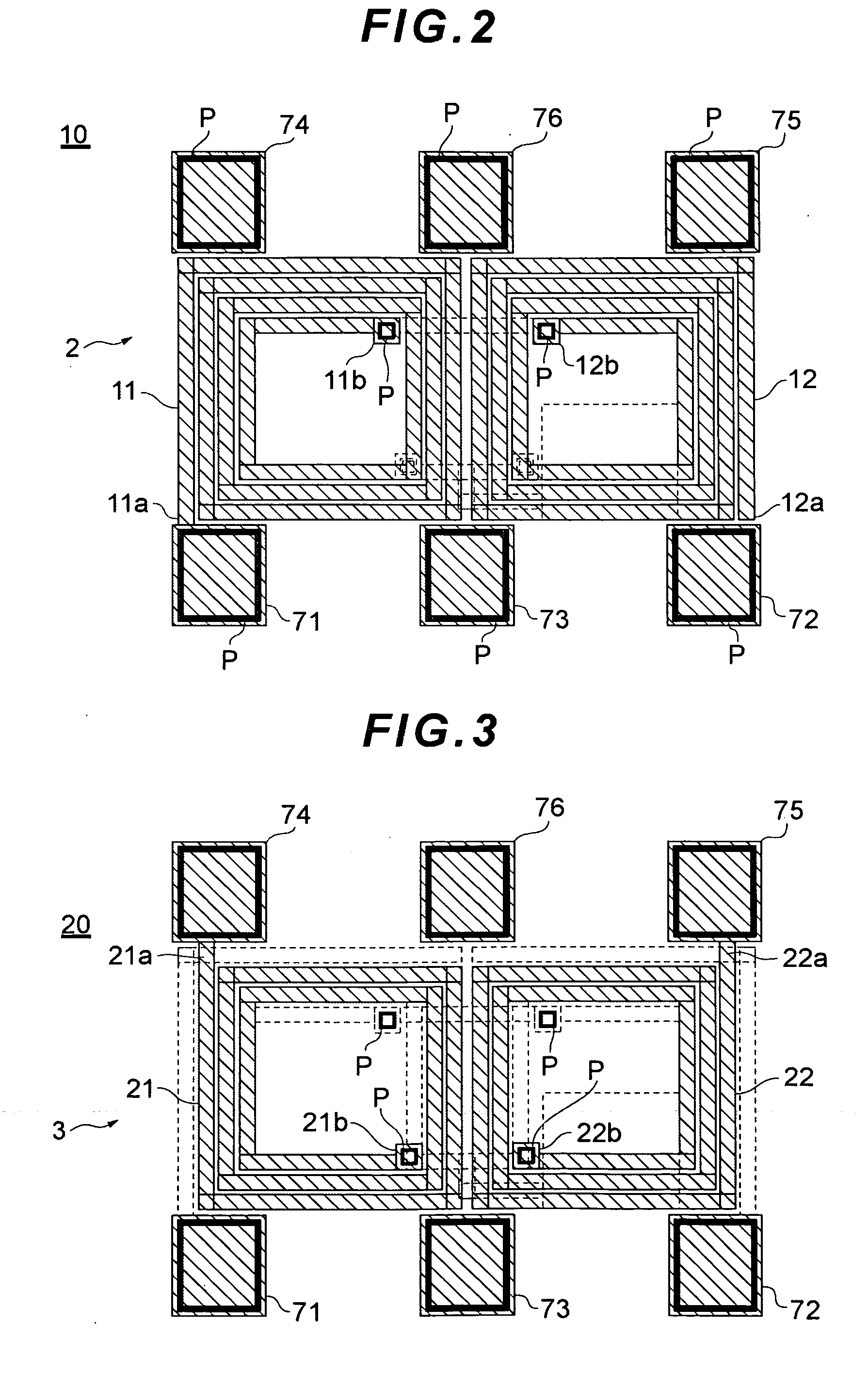
There is provided a thin film balun which, while incorporating a capacitor used to supply a DC bias, allows improvement of various required characteristics.A thin film balun according to the present embodiment includes: an unbalanced transmission line which includes two coils 11 and 12; a balanced transmission line 3 which includes two coils 21 and 22 and which magnetically couples with the unbalanced transmission line; a capacitor 4 having one end connected to the balanced transmission line 3; and a ground terminal 72 connected to the other end of the capacitor 4. The capacitor 4 is disposed to have a region which does not overlap a part of coil openings C1 and C2 defined by the coils 11 and 12 and the coils 21 and 22.

Description

BACKGROUND OF THE INVENTION[0001]1. Field of the Invention[0002]The present invention relates to a balun that performs unbalanced-to-balanced signal conversion, and more particularly to a thin film balun formed by a thin film process which is advantageous for miniaturization and thickness reduction.[0003]2. Description of the Related Art[0004]Radio communication apparatuses include various high frequency elements such as antenna, filter, RF switch, power amplifier, RF-IC and balun. Here, resonant elements such as antenna and filter handle unbalanced signals relative to the ground potential; however, RF-IC, which produces or processes high frequency signals, handles balanced signals. Thus, in connecting the two types of elements, a balun is used which functions as an unbalanced-to-balanced signal converter.[0005]Sometimes a balanced signal needs to be amplified by applying a bias to a balun used in mobile communication equipment such as mobile-phone and wireless LAN. In this case, be...

Claims


Application Information

Patent Timeline
IPC IPC(8): H03H5/00
CPCH01P5/10H03H2001/0085H03H7/422
Inventor ENDO, MAKOTO
Owner TDK CORPARATION
Learn More