
Cable

Pending Publication Date: 2022-03-17
PROTERIAL LTD
View PDF1 Cites 0 Cited by
  • Summary
  • Abstract
  • Description
  • Claims
  • Application Information

AI Technical Summary

Benefits of technology

The invention provides a cable that is lightweight, easy to wire, and has metal wires that are resistant to breaking when the cable is bent.

Problems solved by technology

Thus, the cable including a braided shield formed by braiding metal wires made of copper or copper alloy as a shield layer may be extremely heavy (for example, approximately 30% of a total copper amount in the cable may be a copper amount of the shield layer).
Thus, for example, it is hard to wire the cable with being bent in a desired shape based on a wiring space in the wiring operation of the cable, or it is hard to transport the cable while the cable is received compactly in a housing case and the like, so that the handling property of the cable may be decreased.
In this case, although the weight of the cable will be lighter, abrasion of the metal wires due to the friction between metal wires will be easily caused in bending the cable, and the disconnection (breakage) of the metal wires may easily occur.
If the metal wire constituting the shield layer is broken, the function as the shield layer will be deteriorated.

Method used


Image

  • Cable

Examples


embodiment

[0020]An embodiment of the present invention will be explained in conjunction with appended drawings.

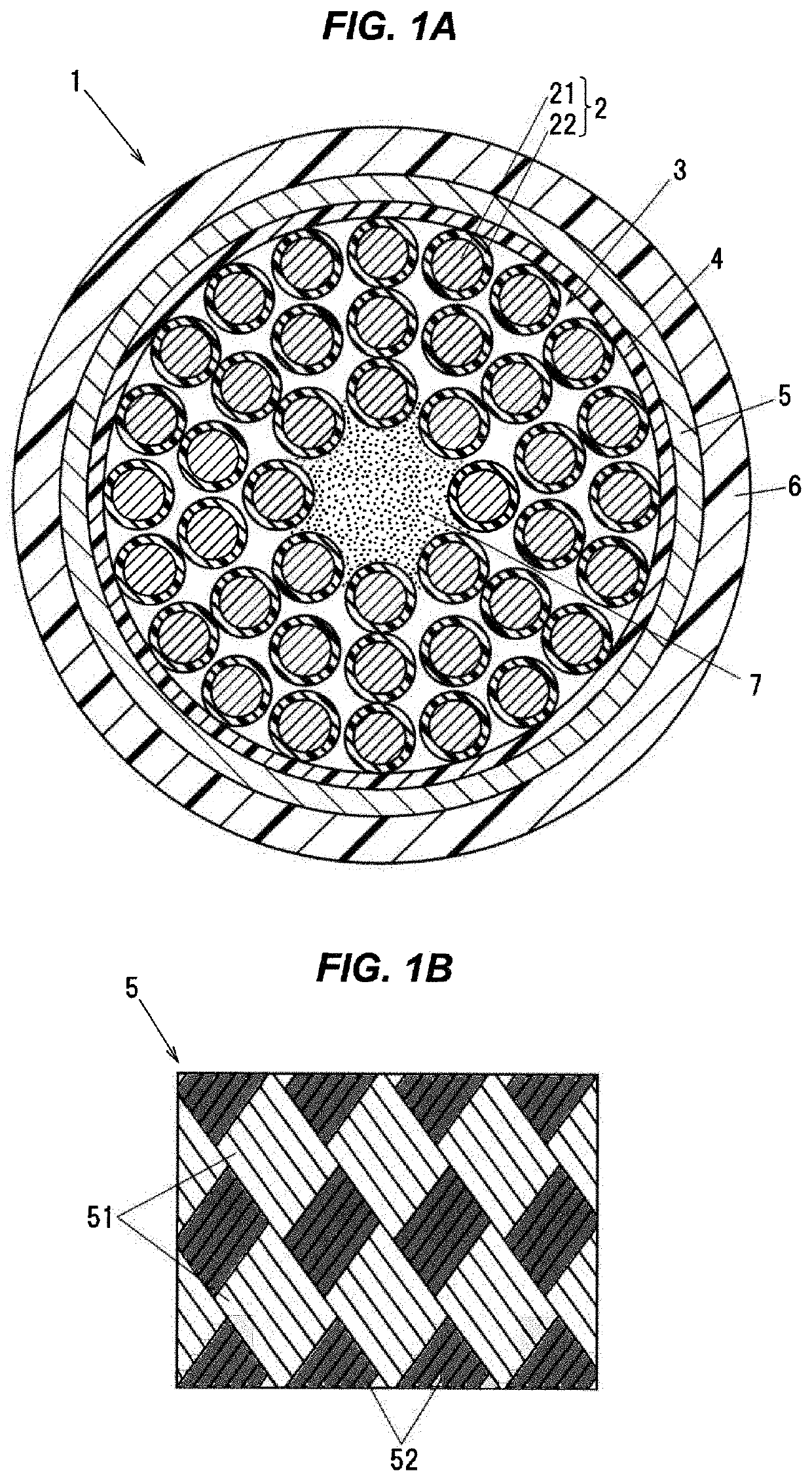
[0021]FIG. 1A is a cross-sectional vies showing a cross-section perpendicular to a cable longitudinal direction of a cable according to an embodiment of the present invention. FIG. 1B is a schematic diagram showing a shield layer. A cable 1 is, for example, used as a fixed part cable for connecting between an industrial robot and a control device or the like in factories and the like.

[0022]As shown in FIGS. 1A and 1B, the cable 1 comprises a cable core 3 comprising one or more electric wires 2, a shield layer 5 covering around the cable core 3, and a sheath 6 covering around the shield layer 5.

[0023]The electric wire 2 comprises a conductor 21, and an insulator 22 covers around the conductor 21. The conductor 21 is composed of a stranded conductor formed by twisting a plurality of metal wires together. In the present embodiment, the conductor 21 is formed by collectively twisting thi...


PUM


Abstract

A cable includes a cable core including one or more electric wires, a shield layer covering around the cable core, and a sheath covering around the shield layer. The shield layer is composed of a braided shield including a plurality of first metal wires composed of aluminum or aluminum alloy and a plurality of second metal wires composed of copper or copper alloy. The plurality of first metal wires and the plurality of second metal wires are cross-braided.

Description

CROSS-REFERENCE TO RELATRED APPLICATION[0001]The present application is based on Japanese patent application No. 2020-154344 filed on Sep. 15, 2020, the entire contents of which are incorporated herein by reference.BACKGROUND OF THE INVENTION1. Field of the Invention[0002]The present invention relates to a cable.2. Description of the Related Art[0003]In order to enhance productivity in a factory or the like, the widespread use of industrial robots such as cooperative robots or small articulated robots or the like is expanding. As a cable being used for the industrial robots, a movable part cable to be wired in a movable part of the industrial robot and a fixed part cable for connecting between the industrial robot and a control device or the like have been known. As an example of a cable being used as the fixed part cable, a cable including a shield layer around a cable core so as to suppress an external noise in factories and the like has been used. As the shield layer, a braided s...

Claims


Application Information

Patent Timeline
IPC IPC(8): H01B11/20H01B11/18H01B7/18H01B7/22
CPCH01B11/20H01B7/22H01B7/1865H01B11/1808H01B7/17H01B7/041H01B7/40H01B11/1033H01B7/228
Inventor HUANG, DETIANTSUKAMOTO, YOSHINORIKOBAYASHI, MASANORIMORIYAMA, MASASHIFUKUZATO, KOJI
Owner PROTERIAL LTD
Learn More