Rotor for a rotary electric machine

a rotary electric machine and rotor technology, applied in the direction of dynamo-electric machines, magnetic circuit rotating parts, magnetic circuit shape/form/construction, etc., can solve the problems of reducing mechanical performance, non-magnetic metal material end discs (such as stainless steel) not being able to properly keep lamination sheets, and worsening the energetic efficiency of electric machines

Active Publication Date: 2019-09-19
MARELLI EURO SPA
View PDF8 Cites 4 Cited by
  • Summary
  • Abstract
  • Description
  • Claims
  • Application Information

AI Technical Summary

Problems solved by technology

However, when the size of the rotor increases, manufacturing the end discs with a non-magnetic metal material (such as stainless steel) has proved to lead to drawbacks, as non-magnetic metal materials usually deliver reduced mechanical performances; as a consequence, end discs made of a non-magnetic metal material (such as stainless steel) are not capable of properly keeping the lamination sheets making up the magnetic core stacked together.
In other words, when the size of the rotor increases, the end discs made of a non-magnetic metal material tend to plastically deform (namely, to yield) due to the mechanical stresses produced by the rotation, thus causing the lamination sheets making up the magnetic core to loose their compact arrangement.
However, the end discs made of a magnetic metal material are affected by relevant power losses due to parasitic currents and, hence, determine a worsening of the energetic efficiency of the electric machine.
In large-sized electric machines, ends discs were suggested, which are made of a special metal material, which is non-magnetic, though has good mechanical features, or of a non-metal material, which has good mechanical features; however, this solution leads to a significant increase both in the manufacturing costs of the end discs and in the processing costs arising from the coupling of the end discs to the shaft.

Method used


Image

  • Rotor for a rotary electric machine
  • Rotor for a rotary electric machine
  • Rotor for a rotary electric machine

Examples


Embodiment Construction

[0015]The object of the invention is to provide a rotor for a rotary electric machine, which is not affected by the aforementioned drawbacks and, at the same time, can be manufactured in a straightforward and low-cost manner.

[0016]According to the invention, there is provided a rotor for a rotary electric machine according to the appended claims.

[0017]The appended claims describe preferred embodiments of the invention and form an integral part of the description.

BRIEF DESCRIPTION OF THE DRAWINGS

[0018]The invention will now be described with reference to the accompanying drawings, showing a non-limiting embodiment thereof, wherein:

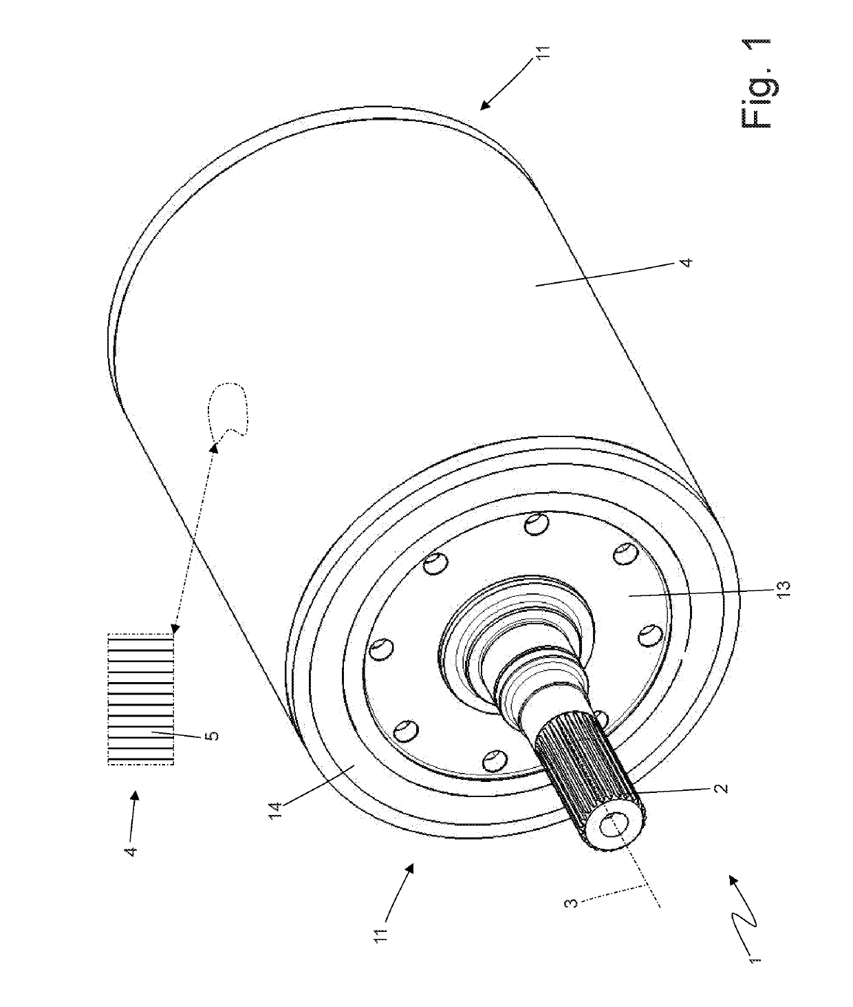
[0019]FIG. 1 is a perspective view of a rotor for a rotary electric machine manufactured according to the invention;

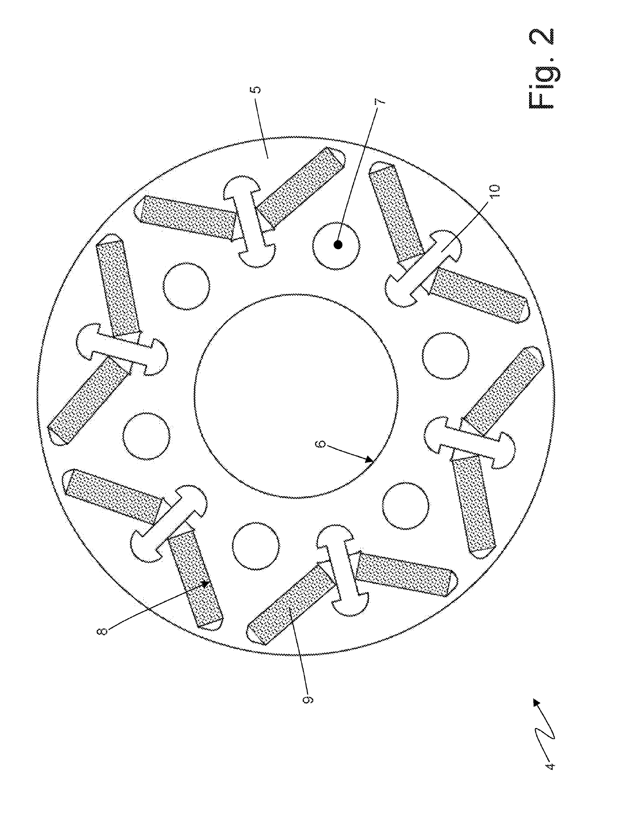
[0020]FIG. 2 is a cross section view of a magnetic core of the electric machine of FIG. 1;

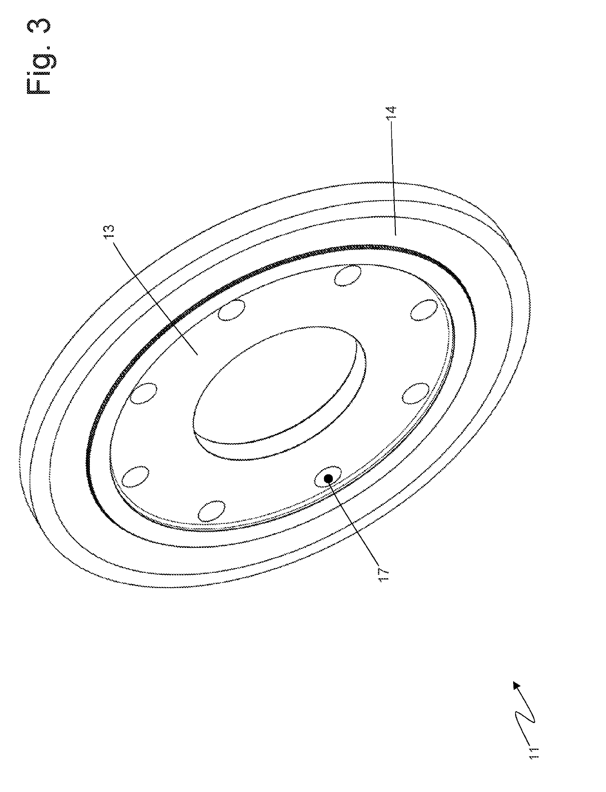
[0021]FIGS. 3 and 4 are two different perspective views of an end disc of the electric machine of FIG. 1;

[0022]FIGS. 5 and 6 are two different perspectiv...


PUM


Abstract

A rotor for a rotary electric machine; the rotor has: a shaft, which is mounted so as to rotate around a rotation axis; a magnetic core, which is arranged around the shaft and consists of a plurality of lamination sheets stacked together; and a pair of end discs, which are arranged around the shaft at the two opposite ends of the magnetic core and are designed to keep the lamination sheets of the magnetic core stacked together; wherein the end discs are designed to have balancing holes, which dynamically balance the rotor around the rotation axis. Each end disc consists of an inner component with an annular shape, which is arranged around the shaft and is made of a first metal material, and of an outer component with an annular shape, which is arranged around the inner component and is made of a second metal material, which is different from the first metal material and is non-magnetic.

Description

CROSS-REFERENCE TO RELATED APPLICATIONS[0001]This patent application claims priority from Italian patent application no. 102018000003491 filed on Mar. 13, 2018 the entire disclosure of which is incorporated herein by reference.TECHNICAL FIELD[0002]The invention relates to a rotor for a rotary electric machine.[0003]The invention can advantageously be applied to a rotor with permanent magnets for a rotary electric machine for vehicle powering, to which explicit reference will be made in the description below without because of this loosing in generality.PRIOR ART[0004]A rotary electric machine comprises a shaft, which is mounted so as to rotate around a rotation axis, a rotor, which has an annular cylindrical shape and is rigidly fixed to the shaft, and a stator, which has an annular cylindrical shape and is arranged without contact (namely, with a magnetic gap of a few millimetres) around the rotor (namely, houses the rotor on the inside).[0005]In order to allow the rotary electric ...

Claims


Application Information

Patent Timeline
Patent Type & Authority Applications(United States)
IPC IPC(8): H02K7/04H02K1/28H02K1/27
CPCH02K7/04H02K1/28H02K1/276H02K1/02H02K1/2766
Inventor MAGRI, MARCOLELI, FRANCESCOSTAMATO, SALVATORE
Owner MARELLI EURO SPA
Why Eureka
Try Eureka