Motor mounting structure for electric seat sliding device

Active Publication Date: 2019-09-26
TF METAL CO LTD
View PDF5 Cites 1 Cited by
  • Summary
  • Abstract
  • Description
  • Claims
  • Application Information

AI Technical Summary

Benefits of technology

The invention provides a motor mounting structure for an electric seat sliding device that solves problems with existing structures. The structure simplifies the shape of the motor support bracket, decreasing cost and allowing for automation. This results in a more efficient and cost-effective assembly process.

Problems solved by technology

Accordingly, the workability of the assembly operation of the motor is deteriorated.
Moreover, this motor assembling structure is unsuitable for the automation.
Consequently, the man-hour for the press-processing of the bending process and the perforating process is increased to increase the cost.

Method used


Image

  • Motor mounting structure for electric seat sliding device
  • Motor mounting structure for electric seat sliding device
  • Motor mounting structure for electric seat sliding device

Examples


Embodiment Construction

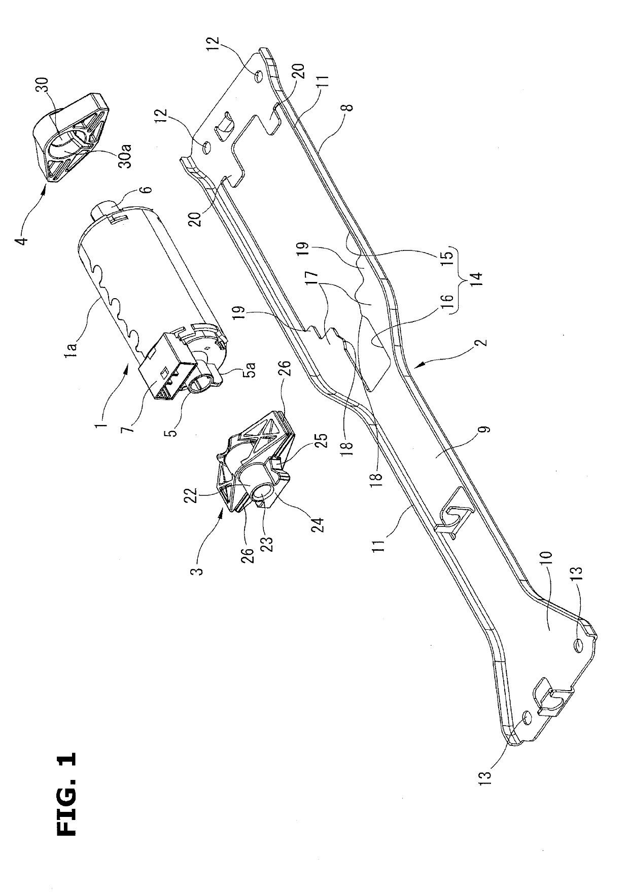
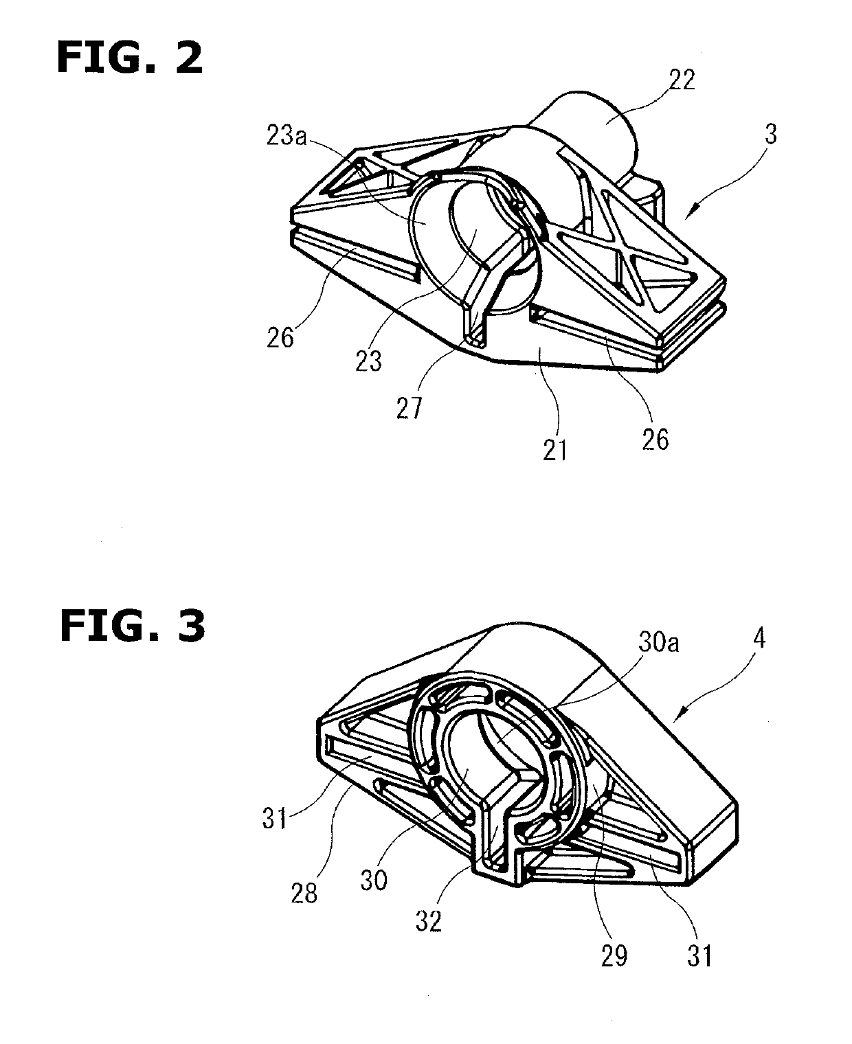
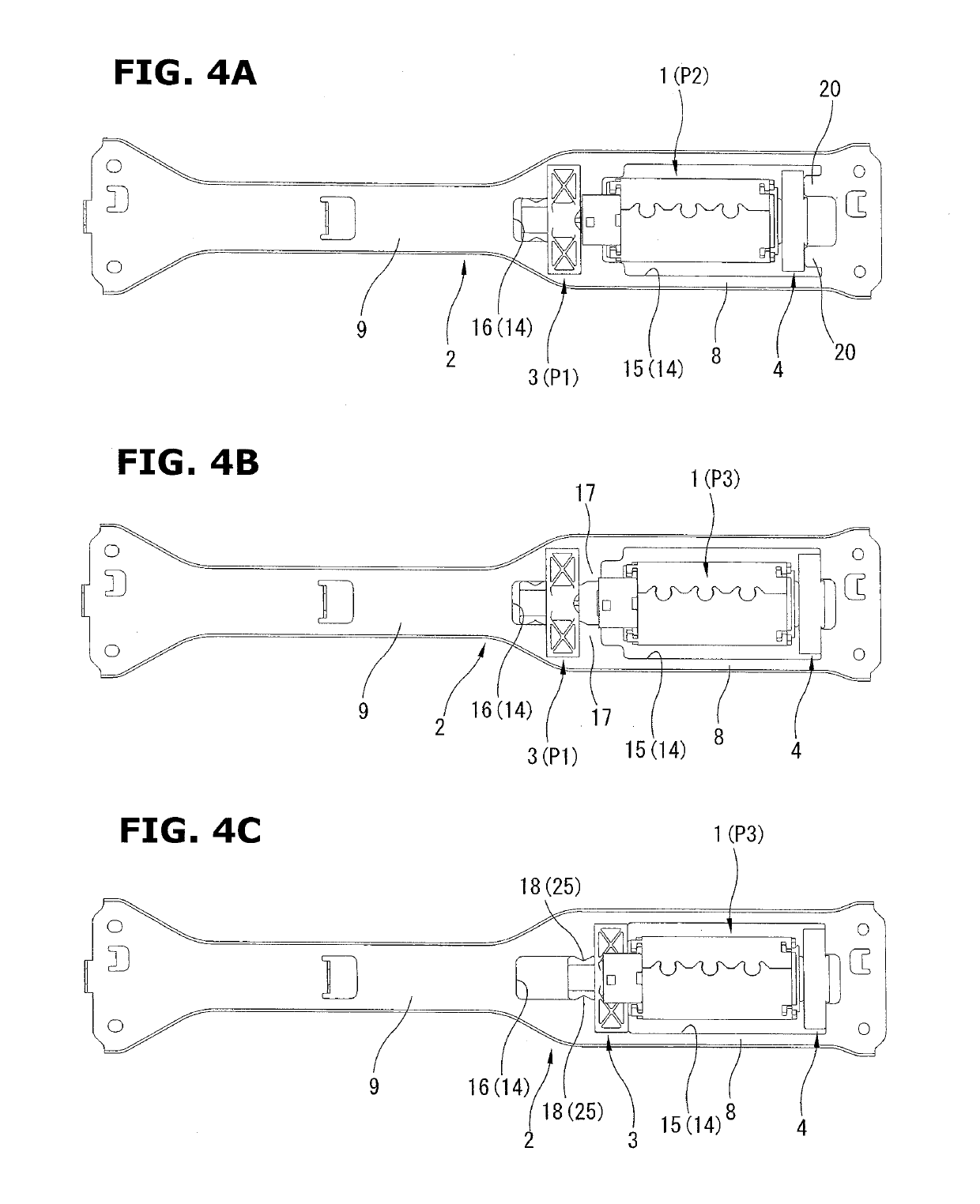
[0011]FIGS. 1 to 4 show a motor mounting structure of an electric seat sliding device according to an embodiment of the present invention. FIG. 1 is an exploded perspective view showing a position relationship among a motor, a bracket, and first and second dampers. FIGS. 2 and 3 are perspective views showing the first and second dampers shown in FIG. 1 when viewed from a direction opposite to the view direction of FIG. 1. Moreover, FIGS. 4A to 4C are plan views showing an assembly process in the structure shown in FIG. 1.

[0012]The motor mounting structure shown in FIG. 1 includes a motor 1 which is an electric driving source of the electric seat sliding device; and a bracket 2 supporting this motor 1; and a first damper 3 and a second damper 4 which are first and second elastic support members, and which are disposed between the bracket 2 and the motor 1 when the bracket 2 supports the motor 1.

[0013]The motor 1 has a cylindrical shape. The motor 1 includes a cylindrical motor case 1...


PUM


Abstract

A motor mounting structure for an electric seat sliding device includes: a motor; first and second elastic support members arranged to be mounted on the first and second protruding portions of the motor; a bracket arranged to support the both ends of the motor through the first and second elastic support members; and the second elastic support member being arranged to be moved between a position at which the second elastic support member is engaged with the second guide portion, and a position where the second elastic support member is disengaged from the second guide portion, and where the second elastic support portion is mounted on the second protruding portion of the motor positioned at the initial assembly position.

Description

BACKGROUND OF THE INVENTION[0001]The present invention relates to a motor mounting structure for an electric seat sliding device mounted on a vehicle.[0002]A Japanese Patent Application Publication No. 2001-334858 (corresponding to U.S. Patent Application Publication No. 2001 / 0048058 A1) discloses a motor mounting structure for an electric seat sliding device. This motor mounting structure includes a pair of left and right upper rails which extends on left and right sides of a seat in a seat sliding direction; and a motor support bracket which is disposed at a substantially central position in a longitudinal direction of the upper rails, to connect and extend between these upper rails. This motor support bracket includes a pair of support portions elected in a vertical direction. Both end portions of the motor in an axial direction are supported by these support portions through elastic bushes.[0003]Besides, a rotation output of the motor is transmitted to a gear box constituted, fo...

Claims


Application Information

Patent Timeline
IPC IPC(8): B60N2/02
CPCB60N2002/0236B60N2002/024B60N2/0232B60N2/02258B60N2/02246B60N2/067B60N2/02253B60N2205/20
Inventor IMAMURA, TAKASHI
Owner TF METAL CO LTD
Why Eureka
Try Eureka