Wrench width adapter for a component that is screwable into a threaded opening

a technology of threaded opening and wrench, which is applied in the direction of wrenches, instruments, fastening means, etc., can solve the problems of limiting the freedom of configuring and miniaturizing the pressure sensor as well as the installation site of the pressure sensor, so as to achieve the effect of convenient and cost-efficient manufacturing

Active Publication Date: 2019-09-26
ROBERT BOSCH GMBH
View PDF0 Cites 1 Cited by
  • Summary
  • Abstract
  • Description
  • Claims
  • Application Information

AI Technical Summary

Benefits of technology

[0006]Due to the wrench width adapter according to the present invention, components that are screwable into threaded openings on the one hand may advantageously be configured with arbitrarily small wrench widths, and on the other hand may still be screwed in, optionally with the tightening tools used thus far. This may be achieved very easily by inserting the components into the wrench width adapter. The inner wall of the wrench width adapter has a first wrench width dimension that corresponds to the wrench width dimension of an outer circumference of the component base body, so that the wrench width adapter engages with the outer circumference of the component base body in a form-fit manner when the component is inserted. In addition, the wrench width adapter on its outer wall has a second wrench width dimension that may, for example, advantageously correspond to the tightening tools used thus far. The wrench width adapter advantageously provides a number of options for configuring the outer wall with a completely different geometry than the inner wall that is adapted to the component in question. Thus, for example, additional measures such as a locking arrangement or anti-dismantling protection which cannot be provided on the component may also optionally be integrated into the wrench width adapter.
[0007]Advantageous specific embodiments and refinements of the present invention are made possible by the features described in the dependent claims.
[0008]The wrench width adapter advantageously includes a base body on which at least one projection that protrudes into the inner recess is formed. The at least one projection protruding into the inner recess may represent a stop surface for the component when the component is inserted into the inner recess. This advantageously prevents the component from sliding through the inner recess. In addition, the wrench width adapter may advantageously be clamped between the component base body and a countersurface that encloses the threaded opening when the component is screwed into the threaded opening associated with the component, and therefore cannot be lost.
[0009]At least one fastening arrangement for fastening the base body to the component may advantageously be provided on the base body of the wrench width adapter. The at least one fastening arrangement, for example viewed in the direction of the longitudinal axis, may include a tab that protrudes from the base body in the direction of the inner recess on the side of the base body facing away from the at least one projection. The component may thus be advantageously clamped between the projection and the tab so that the wrench width adapter is locked on the component. The at least one fastening arrangement may advantageously be configured as a detent arrangement, a securing lug, or a secured wall section. A detent lug of the detent arrangement then automatically engages behind a projection or a support surface of the component when the component is inserted into the inner recess of the wrench width adapter. When the fastening arrangement is configured as a securing lug, the lug is bent over after the component is inserted, and with its protruding tab engages behind a support surface on the component. In addition, it is possible to configure at least one wall section of the base body in such a way that it may be secured in the direction of the inner recess.
[0010]In one exemplary embodiment, the base body of the wrench width adapter includes a circumferential wall that extends in the longitudinal axis, the inner side of which forms the inner wall and the outer side of which forms the outer wall. Additionally or alternatively, the base body includes a ring-shaped base plate that is perpendicular to the longitudinal axis and which may be configured in one piece with the wall, and that protrudes into the inner recess, thus forming the at least one projection. The base plate is advantageously used for securely supporting the wrench width adapter on a countersurface in which the threaded opening for the at least one component is provided. The base body of the wrench width adapter may be easily and cost-efficiently manufactured from plastic or metal.
[0011]Also advantageous is a combination of the wrench width adapter with a component that is screwable into a threaded opening, and that includes a threaded connector and a component base body that adjoins in the longitudinal axis of the component and whose outer circumference in a cross-sectional plane perpendicular to the longitudinal axis has, at least in part, the shape of a regular polygon corresponding to the first wrench width dimension. The component is advantageously inserted into the receptacle in such a way that the threaded connector is guided through the inner recess, and outwardly protrudes from the base body of the wrench (width) adapter in the direction of the longitudinal axis. The assembly made up of the wrench width adapter and the component may advantageously be delivered and installed as a unit.

Problems solved by technology

However, the wrench width dimension of this hexagon must not be reduced too greatly, since the tool required for the screwing-in then cannot be drawn over the plug part in every case.
This limits the freedom in configuring and miniaturizing the pressure sensor as well as the installation site of the pressure sensor.

Method used


Image

  • Wrench width adapter for a component that is screwable into a threaded opening
  • Wrench width adapter for a component that is screwable into a threaded opening
  • Wrench width adapter for a component that is screwable into a threaded opening

Examples


Embodiment Construction

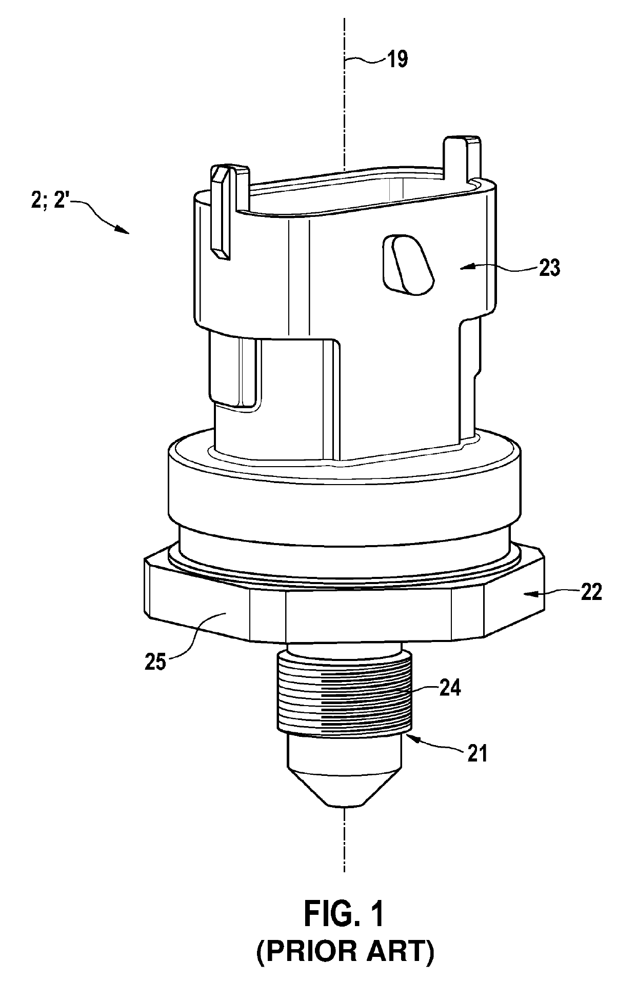
[0022]FIG. 1 shows a pressure sensor 2′ from the related art, for example from EP 1 518 099 B1. Known pressure sensor 2′ includes a component base body 22 or sensor base body whose outer circumference in a cross-sectional plane perpendicular to a longitudinal axis 19 of pressure sensor 2′ has the shape of a regular polygon. In the present example, the polygon forms a hexagon 25, for example. Hexagon 25 has a first wrench width dimension S1. On the bottom side of component base body 22 a threaded connector 21 protrudes from component base body 22. Threaded connector 21, which has a rotationally symmetrical configuration with respect to longitudinal axis 19, includes a screw thread 24 on an outer circumference. Threaded connector 21 is used to screw the pressure sensor into a pressure measurement port, not illustrated. A pressure channel, not discernible in FIG. 1, that passes centrally through threaded connector 21 connects the pressure measurement port to a sensor element in the int...


PUM

PropertyMeasurementUnit
rotation angleaaaaaaaaaa
widthaaaaaaaaaa
width dimensionaaaaaaaaaa

Abstract

A wrench width adapter for a component that is screwable into a threaded opening is provided, including a base body having a continuous inner recess, extending along a longitudinal axis, for receiving the screw-in component. An inner wall of the base body that delimits the inner recess, in a cross-sectional plane perpendicular to the longitudinal axis, has, at least in part, the shape of a regular polygon corresponding to a first wrench width dimension, and an outer wall of the base body has, at least in part, the shape of a regular polygon corresponding to a second wrench width dimension that is greater than the first wrench width dimension.

Description

FIELD OF THE INVENTION[0001]The present invention relates to a wrench width adapter for a component that is screwable into a threaded opening.BACKGROUND INFORMATION[0002]A considerable number of components that are screwable into a threaded opening are believed to be available from the related art, which for this purpose include a threaded connector and a component base body that adjoins in the longitudinal axis of the component, and whose outer circumference in a cross-sectional plane perpendicular to the longitudinal axis has, at least in part, the shape of a regular polygon corresponding to a first wrench width dimension. Customary hexagon head screws are the simplest example of such components. A wrench width dimension, also in the context of the present patent application, is understood to mean the distance between two parallel surfaces of a regular polygon that is used for transmitting a torque with the aid of a form-fit tool. Associated tolerances for internal and external pa...

Claims


Application Information

Patent Timeline
Patent Type & Authority Applications(United States)
IPC IPC(8): F16B37/14B25B13/56G01L19/00B25B13/48G01L19/14
CPCB25B13/56B25B13/48G01L19/14F16B37/14G01L19/0007
Inventor PANHOELZL, BERNHARD
Owner ROBERT BOSCH GMBH
Why Eureka
Try Eureka