Universal joint socket

Inactive Publication Date: 2019-09-26
TSAI JHIH SHENG
View PDF14 Cites 5 Cited by
  • Summary
  • Abstract
  • Description
  • Claims
  • Application Information

AI Technical Summary

Benefits of technology

[0010]The main objective of the present invention is to provide a universal joint socket which can solve the problems that the soc

Problems solved by technology

4. The pin 87 may be loosened during a high speed operation and may be spun away by inertia and injure the user, if

Method used


Image

  • Universal joint socket
  • Universal joint socket
  • Universal joint socket

Examples


Example

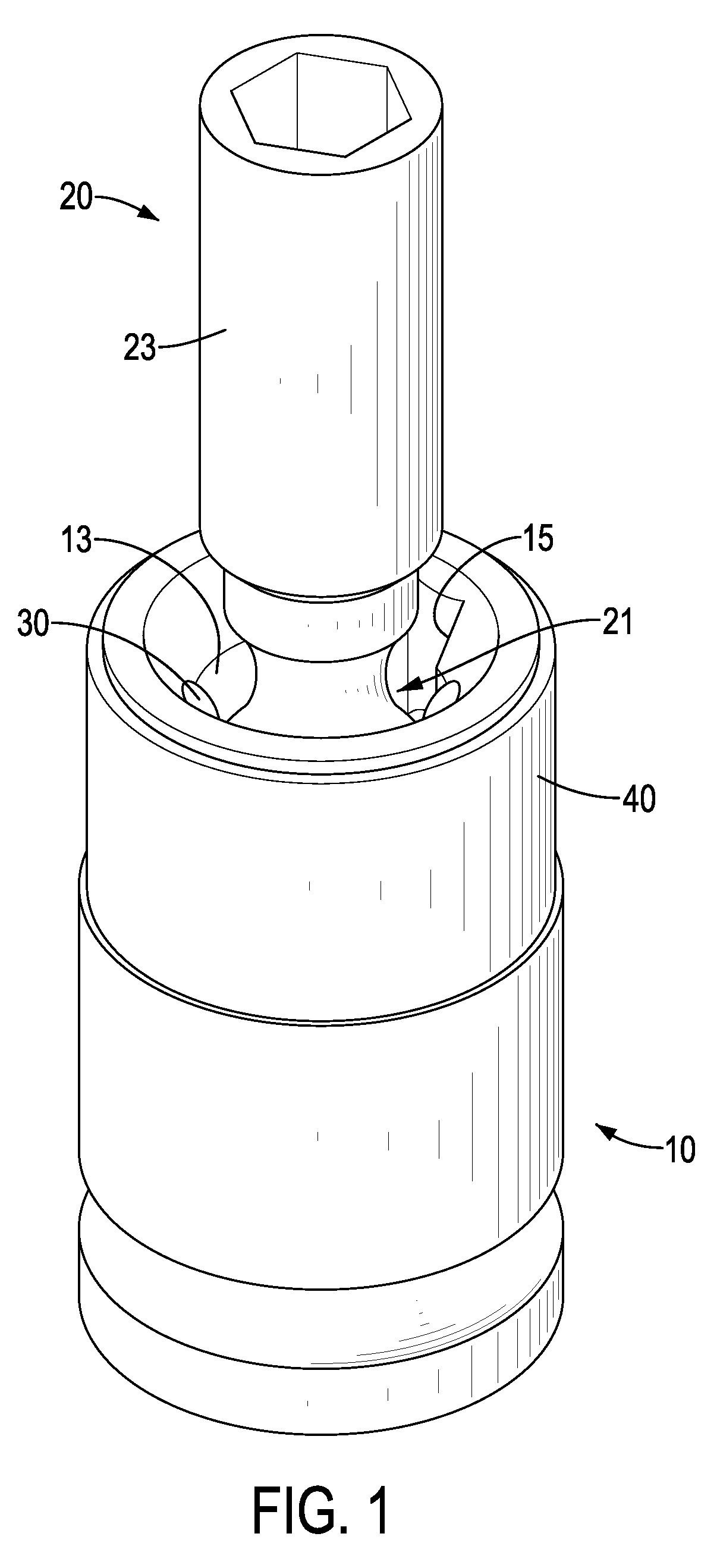
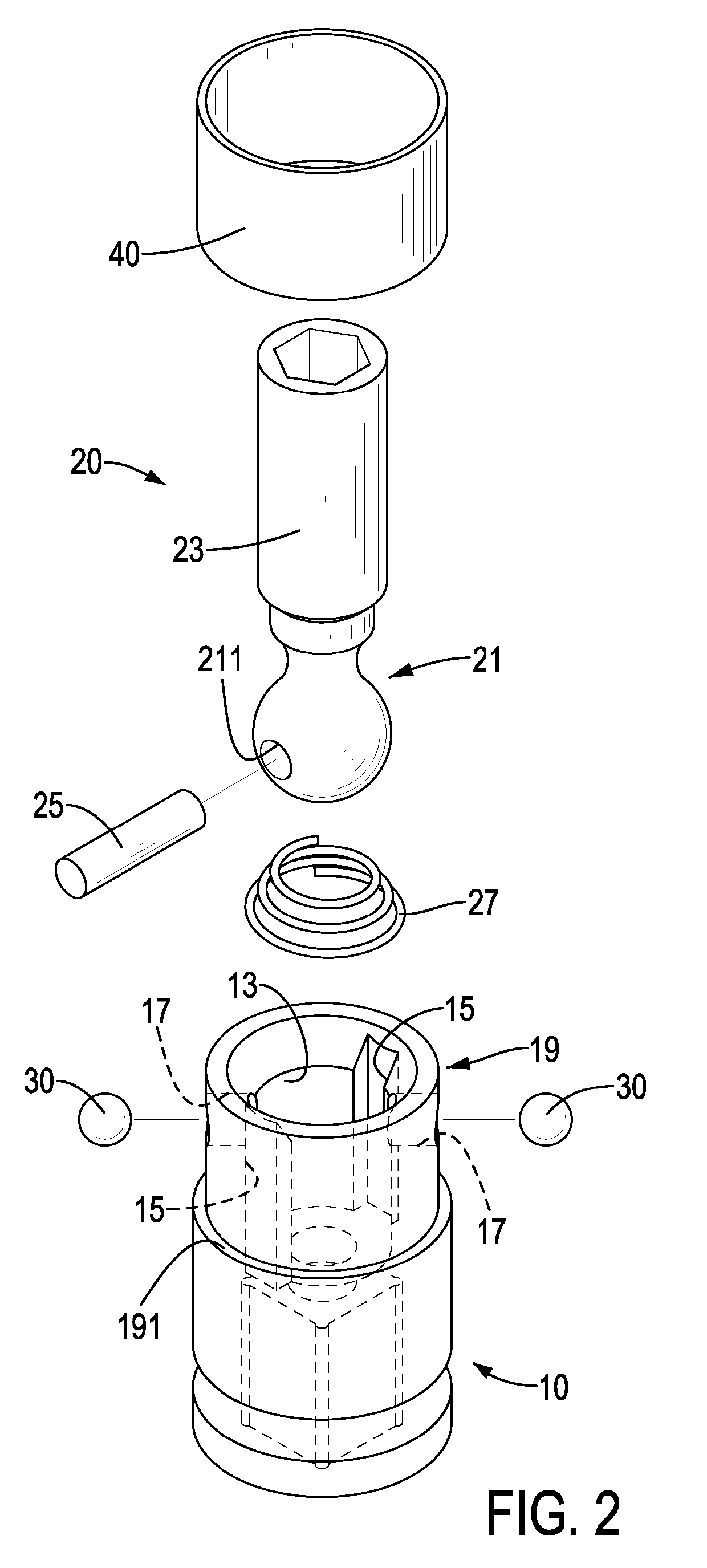
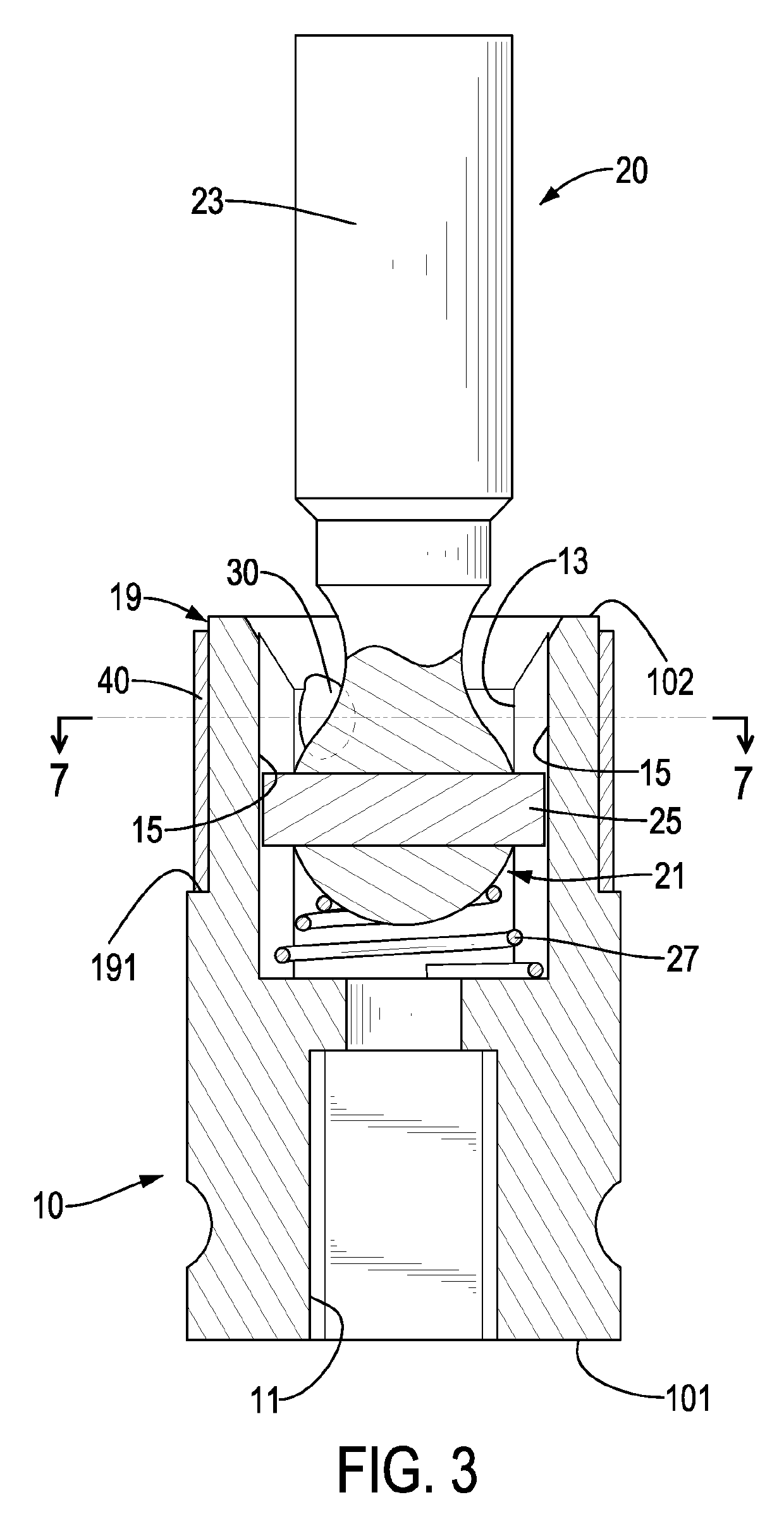
[0029]With reference to FIGS. 1 to 4, a first embodiment of a universal joint socket in accordance with the present invention comprises a socket unit 10, a joint unit 20, a pin 25, an elastic element 27, two balls 30, and a collar 40.

[0030]The socket unit 10 is a hollow cylinder, has a lengthwise direction, a first end 101, a second end 102, a junction 11, an insertion cavity 13, two grooves 15, two ball holes 17, and a collar recess 19. The junction 11 is a square cavity formed in the first end 101 of the socket unit 10 for connecting with a driving device, such as an impact wrench. The insertion cavity 13 is a circular cavity formed in the socket unit 10 and has an opening defined in the second end 102. The two grooves 15 are formed in an inner surface of the insertion cavity 13 at the second end 102 of the socket unit 10, are diametrically opposite each other, and extend from the second end 102 toward the first end 101 of the socket unit 10. Each ball hole 17 is a round through h...

Example

[0034]With reference to FIGS. 5 to 6, a second embodiment of a universal joint socket in accordance with the present invention is substantially same as the first embodiment except that the two grooves 15′ in the socket unit 10′ of the second embodiment are through holes formed through the peripheral wall of the socket unit 10′, are diametrically opposite each other, and communicate with the insertion cavity 13′, each groove 15′ extends longitudinally, and each groove 15′ may be a blind hole, as shown in FIG. 5. The collar recess 19′ may be a part of the peripheral wall of the socket unit 102′ near the second end 102′, and has a limiting shoulder 191′ protruding from a middle of the peripheral wall of the socket unit 10′. The collar 40 is mounted in the collar recess 19′ of the socket unit 10′ and abuts on the limiting shoulder 191′. The collar 40 closes the openings of two ball holes 17′ and closes a part of the openings of the grooves 15′, and the pin 25 is located at the closed pa...

Example

[0035]With reference to FIG. 8, a third embodiment of a universal joint socket in accordance with the present invention is substantially same as the second embodiment except that each of the grooves 15a of the socket unit 10 is a through hole that has an opening defined in the second end 102a of the socket unit 10a, and the elastic element 27a is a sheet metal spring.

[0036]Preferred assembling steps of the first embodiment of a universal joint socket in accordance with the present invention are as follows. 1. The pin 25 is inserted into the pivot hole 211 on the joint unit 20, and the elastic element 27 is placed inside the insertion cavity 13 of the socket unit 10. 2. The two ends of the pin 25 are inserted respectively into the two grooves 15 of the socket unit 10, and the spherical joint 21 is disposed inside the insertion cavity 13 of the socket unit 10. 3. The balls 30 are respectively disposed into the ball holes 17 in the socket unit 10, and the collar 40 is then mounted from...


PUM


Abstract

A universal joint socket has a socket unit, a joint unit, multiple balls, and a collar. The socket unit has a cavity, multiple grooves and multiple ball holes. The joint unit has a spherical joint, and a pin inserted in the spherical joint. The spherical joint is placed inside the cavity of the socket unit with an elastic element inside for supporting the spherical joint, and two ends of the pin are located respectively on the grooves of the socket unit. The balls are respectively disposed in the ball holes of the socket unit for positioning the spherical joint. The collar is mounted around the peripheral wall of the socket unit and closes openings of the ball holes of the socket unit. The universal joint socket has a long operating life and can provide a large torque.

Description

BACKGROUND OF THE INVENTION1. Field of the Invention[0001]The present invention relates to a universal joint socket, and more particularly to a universal joint socket that can provide a large torque.2. Description of Related Art[0002]With reference to FIG. 9, a conventional universal joint socket for a driving device, such as an impact wrench, has a socket unit 80, a joint unit 90, and a pin 87. The socket 80 has a cavity 81 and two pivot holes 83. The joint unit 90 has a spherical joint 91, and a hole 911 formed through the spherical joint 91. The spherical joint 91 of the joint unit 90 is disposed inside the cavity 81 of the socket unit 80, and the pin 87 is inserted through the hole 911 in the spherical joint 91 and the two pivot holes 83 in the socket unit 80. Two ends of the pin 87 are riveted on the peripheral wall of the socket unit 80.[0003]However, the conventional universal joint socket has the following shortcomings:[0004]1. The pin 87 is the weakest and the most often br...

Claims


Application Information

Patent Timeline
IPC IPC(8): F16C11/06F16C11/12
CPCF16C11/12F16C11/0623F16D3/2052F16C11/0652
Inventor TSAI, JHIH-SHENG
Owner TSAI JHIH SHENG
Why Eureka
Try Eureka