
Capsule system for deep geologic disposal of nuclear waste

a geologic and nuclear waste technology, applied in the field of nuclear waste disposal, can solve the problems of high cost of surface operation, prone to human-induced accidental problems, and high cost of both processes, so as to increase the total volumetric capacity of the disposal system, the effect of improving the safety and economics of disposal and long-lasting disposal

Active Publication Date: 2019-09-26
CRICHLOW HENRY
View PDF1 Cites 9 Cited by
  • Summary
  • Abstract
  • Description
  • Claims
  • Application Information

AI Technical Summary

Benefits of technology

The patent text describes a method of disposing of nuclear waste in underground rock formations. The waste is stored in capsules which are then placed in horizontal wellbores in deep underground rock formations. The capsules are designed to be long-lasting and safe, with a minimum risk of degradation and migration of material away from the nuclear waste. The technique uses a combination of geological analysis and technical features to protect the nuclear waste from contact with the biosphere for millions of years. The technical effects include safer, more economical, and long-lasting disposal of the nuclear waste and a reduction of negative impacts on the biosphere.

Problems solved by technology

This surface operation is very costly typically costing hundreds of millions of dollars annually.
These fuel assemblies are highly radioactive and also thermally active and continue to generate sensible heat which must be safely removed by maintaining these assemblies in cooling tanks at the onsite surface storage site.
Both processes present a variety of technical challenges.
Due to the radioactivity and toxicity of the wastes, separation can be both hazardous, very expensive and prone to human-induced accidental problems.
The cost associated with these two primary methodologies is prohibitive.

Method used


Image

  • Capsule system for deep geologic disposal of nuclear waste
  • Capsule system for deep geologic disposal of nuclear waste
  • Capsule system for deep geologic disposal of nuclear waste

Examples


Embodiment Construction

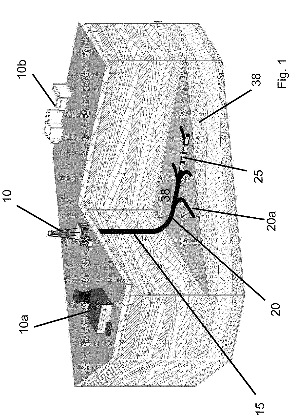
[0104]In this patent application the terms “HLW” and “SNF” describing nuclear (solid) waste may also be used interchangeably herein.

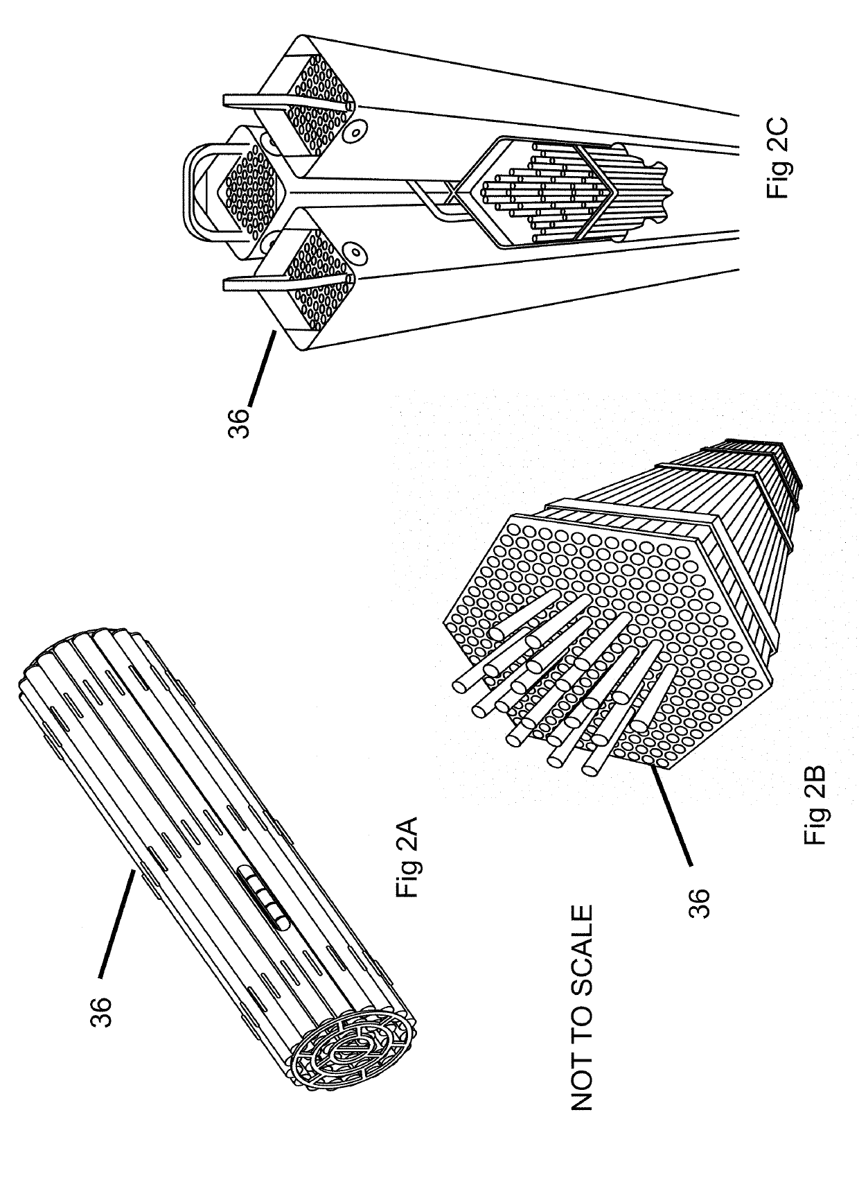
[0105]In this patent application the terms “capsule,”“carrier tube,” and “canister” may be used interchangeably with the same meaning. For example, “waste-capsule 25” and “carrier tube 34” may be used interchangeably.

[0106]In this patent application the terms “tube” and “pipe” may be used interchangeably and refer to cylindrical elements implemented in design and / or installation processes of some embodiments of the present invention.

[0107]Note, unless an explicit reference of “vertical wellbore” or “lateral wellbore” (i.e., “horizontal wellbore”) accompanies “wellbore,” use of “wellbore” herein without such explicit reference may refer to vertical wellbores or lateral wellbores, or both vertical and lateral wellbores.

[0108]In this patent application the terms “wellbore” and “borehole” may be used interchangeably. In some embodiments, initial lateral bor...


PUM


Abstract

Systems and methods for long-term disposal of high-level nuclear waste in deep geologic formations are described. Such systems and methods may include largely intact spent nuclear fuel rod assemblies that may be placed into waste-capsules (e.g., carrier tubes); which may then be placed into various well boreholes. Example embodiments may provide waste-capsules capable of containing and disposing of nuclear waste generated from spent nuclear fuel; including means for harvesting the nuclear waste from cooling pools and / or surface storage; and operationally processing the waste fuel assemblies for inclusion in the waste-capsules with various engineered barriers; along with storage in relatively large substantially horizontal well boreholes; which may be drilled into closed deep geologic formations.

Description

PRIORITY NOTICE[0001]The present application claims priority under 35 U.S.C. § 120 to U.S. non-provisional patent application Ser. No. 15 / 480,504 filed on Apr. 6, 2017. This patent application is a continuation-in-part (CIP) application of the co-pending application Ser. No. 15 / 480,504 filed on Apr. 6, 2017. The present application is related to previous patents by the same inventor related to the disposal of nuclear waste in deep underground formations. These patents are: U.S. Pat. Nos. 5,850,614, 6,238,138, and 8,933,289. The disclosures of all of these patents and co-pending patent application are all incorporated herein by reference in their entirety.TECHNICAL FIELD OF THE INVENTION[0002]The present invention relates generally to disposing of nuclear waste and more particularly, to: (a) the operations of nuclear waste disposal; and (b) utilization of specialized capsules or containers for nuclear waste which may be sequestered in lateral wellbores drilled into deep geologic form...

Claims


Application Information

Patent Timeline
Patent Type & Authority Applications(United States)
IPC IPC(8): G21F9/36
CPCB09B1/008G21F9/36G21F5/005
Inventor CRICHLOW, HENRY
Owner CRICHLOW HENRY
Learn More