
Caul plates that define channels for distributing resin to composite parts

a technology of caul plate and composite parts, which is applied in the field of caul plate for composite parts, can solve the problems of complex process and complex process of infusing resin into a preform, and achieve the effect of reducing cost and saving tim

Active Publication Date: 2019-10-03
THE BOEING CO
View PDF1 Cites 2 Cited by
  • Summary
  • Abstract
  • Description
  • Claims
  • Application Information

AI Technical Summary

Benefits of technology

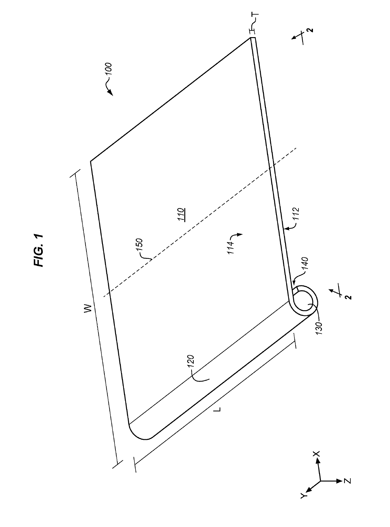
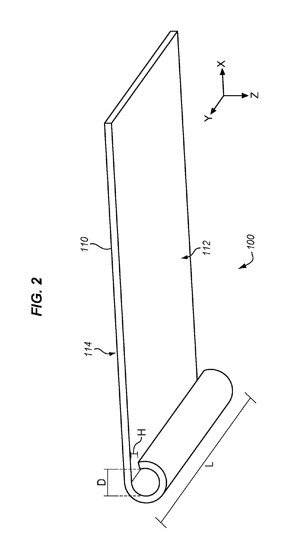
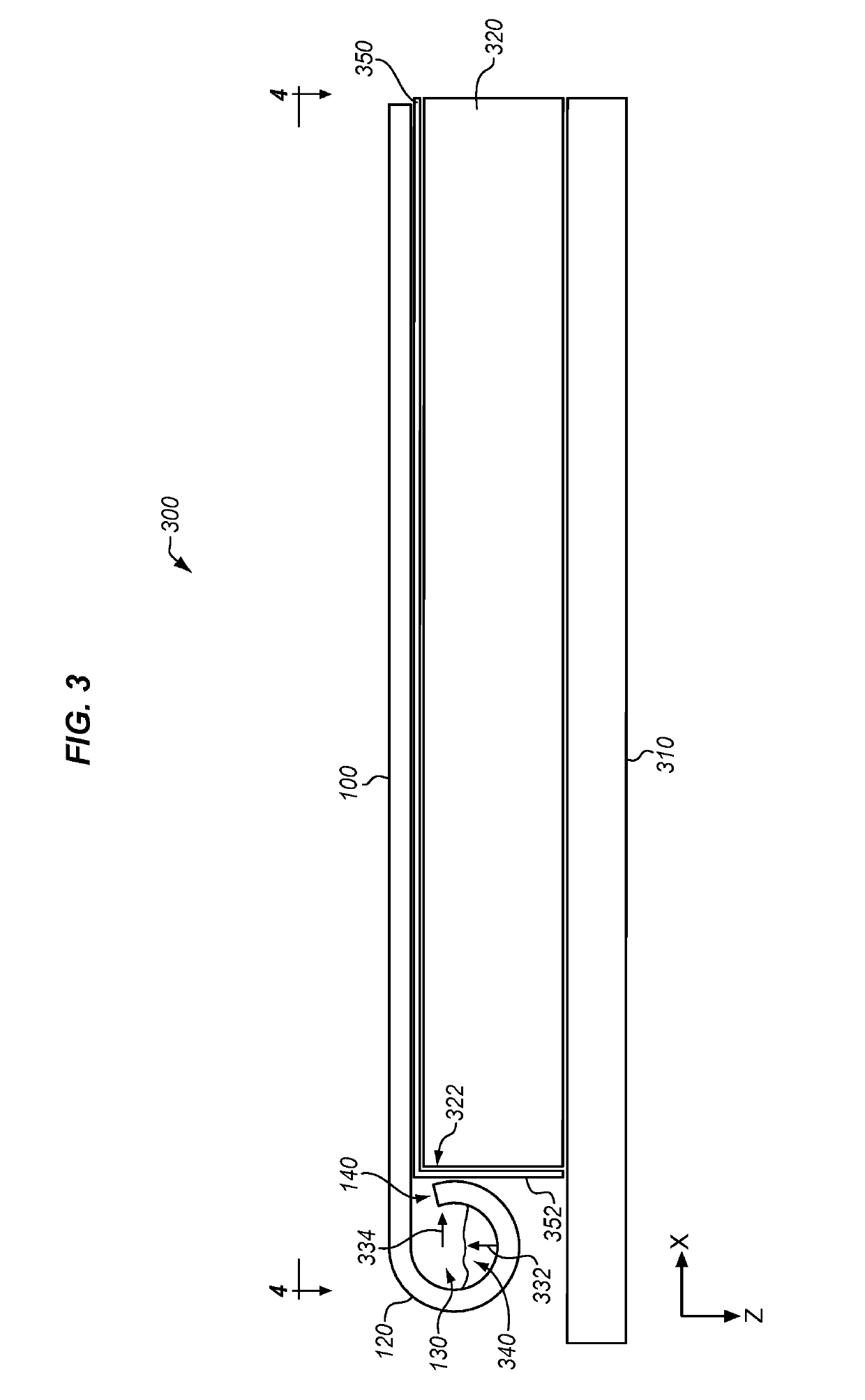
This patent describes a new product called caul plates that have channels built in to them for distributing resin. This eliminates the need for temporary distribution media, which saves time and money. It also ensures that the resin distribution is always aligned with the caul plate, which improves the quality of the parts being made.

Problems solved by technology

However, the process of infusing resin into a preform remains a complicated process that requires the use of sacrificial resin distribution media.
This process is complicated for preforms that use a caul plate, because the distribution media must be carefully laid-up and aligned each time a preform is fabricated, which is time consuming.

Method used


Image

  • Caul plates that define channels for distributing resin to composite parts
  • Caul plates that define channels for distributing resin to composite parts
  • Caul plates that define channels for distributing resin to composite parts

Examples


Embodiment Construction

[0038]In the following examples, additional processes, systems, and methods are described in the context of a composite fabrication system.

[0039]FIG. 8 is a block diagram of a composite fabrication system 800 in an illustrative embodiment. According to FIG. 8, composite fabrication system 800 includes pump 810 which applies vacuum via port 820. For example, pump 810 may apply a full vacuum, or a differential pressure in a range between one half and one atmosphere. The infusion pressure for the resin may vary. Vacuum bag 830 is gas-impermeable, and covers the caul plate 840. Body 848 of caul plate 840 is directly atop peel ply 850, which facilitates the release of caul plate 840 from preform 860. Trough 842 of caul plate 840 defines channel 844, through which resin from reservoir 870 flows. Opening 846 is aligned with preform 860, such that resin from channel 844 may flow into preform 860. Mandrel 880 is located beneath preform 860. In one embodiment, pump 810 and reservoir 870 inclu...


PUM

PropertyMeasurementUnit
thicknessaaaaaaaaaa
pressureaaaaaaaaaa
differential pressureaaaaaaaaaa

Abstract

Systems and methods are provided for fabricating composite parts. One embodiment is a method that includes selecting a caul plate having a body and a trough disposed at a side of the body which defines a channel that hangs beneath the body, the caul plate further having an opening disposed between the trough and the lower surface to form a fluid pathway for resin within the channel to exit into a preform. The method also includes placing the caul plate atop a preform of dry fiber and aligning the channel with a periphery of the preform, placing resin into the trough, and impregnating the preform with resin from the trough.

Description

FIELD[0001]The disclosure relates to the field of composite parts, and in particular, to caul plates for composite parts.BACKGROUND[0002]Composite parts, such as Carbon Fiber Reinforced Polymer (CFRP) parts, are initially laid-up in multiple layers that together form a laminate. Individual fibers within each layer of the laminate are aligned parallel with each other, but different layers may exhibit different fiber orientations in order to increase the strength of the resulting composite along different dimensions. In further composite parts, fibers may be woven or braided, resulting in multiple fiber directions per layer. The laminate may include a liquid resin, such as a thermoset or thermoplastic resin that solidifies in order to harden the laminate into a composite part (e.g., for use in an aircraft). Carbon fiber that has been impregnated with an uncured thermoset resin or a thermoplastic resin is referred to as “prepreg.” Other types of carbon fiber include “dry fiber” which h...

Claims


Application Information

Patent Timeline
Patent Type & Authority Applications(United States)
IPC IPC(8): B29C70/54B29C70/34
CPCB29L2031/3076B29C70/548B29C70/342B29K2101/10B29K2995/0096B29C70/549B29C70/48
Inventor OSBORNE, MAXMCBAIN, JASON
Owner THE BOEING CO
Learn More