Cutting device

a cutting device and cutting blade technology, applied in the direction of typewriters, printing, metal working devices, etc., can solve the problems of insufficient load to be applied to and the cutting of printable tape may not be substantial, so as to achieve the effect of substantial load

Active Publication Date: 2019-10-03
BROTHER KOGYO KK
View PDF0 Cites 0 Cited by
  • Summary
  • Abstract
  • Description
  • Claims
  • Application Information

AI Technical Summary

Benefits of technology

[0006]The present disclosure is advantageous in that a cutting device capable of applying a substantial load on a printing medium while a size of the cutting device is reducible is provided.

Problems solved by technology

With the deformed supporting member, a load from the blade to be applied to the printable tape may not be enough, and the printable tape may not be cut to a substantial amount.

Method used


Image

  • Cutting device
  • Cutting device
  • Cutting device

Examples


Embodiment Construction

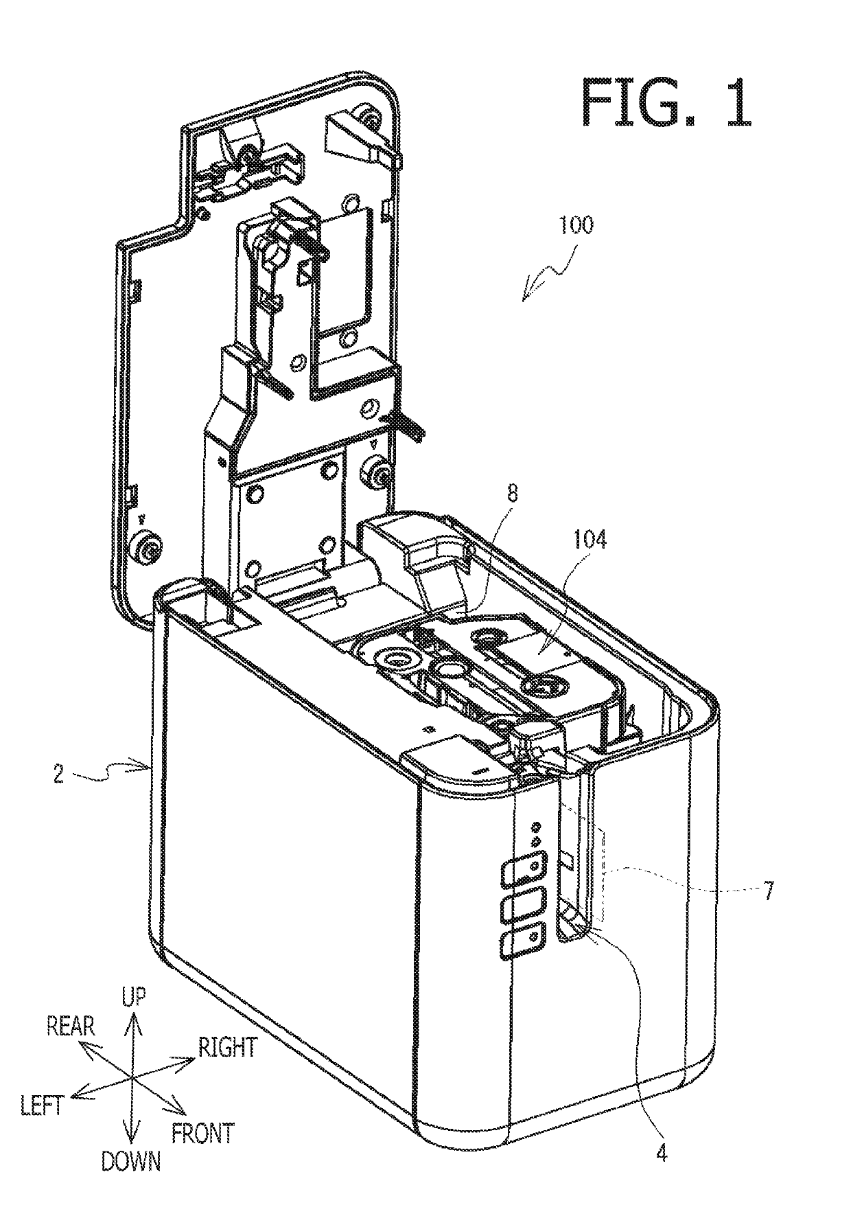
[0018]Hereinafter, with reference to the accompanying drawings, described below will be a printing apparatus 100 according to the embodiment of the present disclosure. It may be noted that structures of the printing apparatus 100 according to the present disclosure may not necessarily be limited to those shown in the accompanying drawings or described in the paragraphs below but may be regarded as merely an example.

[0019]In the embodiment described below, directions related the printing apparatus 100 and parts and members included in the printing apparatus 100 will be mentioned on basis of a posture of the printing apparatus 100 with reference to arrows in each drawing. A front-to-rear or rear-to-front direction may be expressed as a front-rear direction, an up-to-down or down-to-up direction may be expressed as a vertical direction, and a left-to-right or right-to-left direction may be expressed as a crosswise direction.

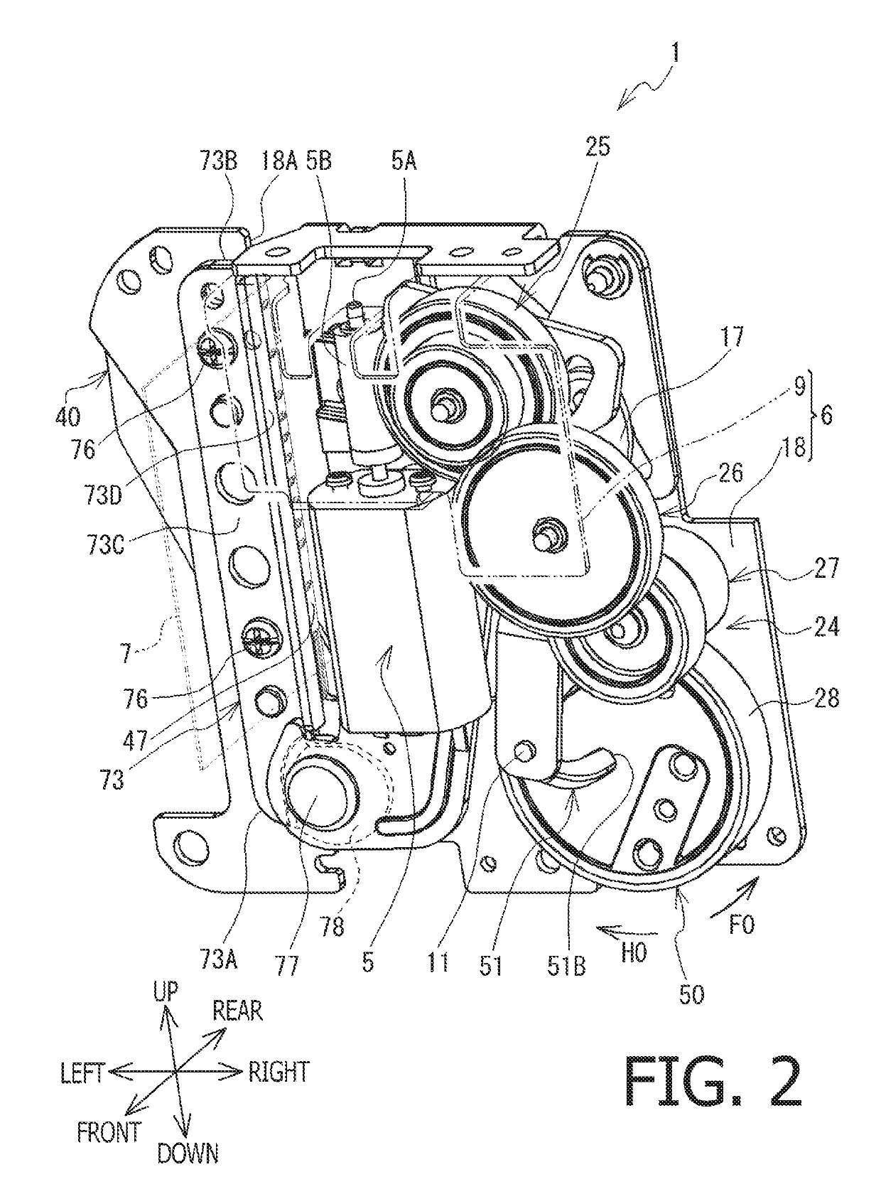
[0020]With reference to FIGS. 1 and 2, described below will be...


PUM


Abstract

A cutting device, including a rotating body, a first link member, a second link member, a placement part, and a movable blade holder, is provided. The first link member is swingable by rotation the rotating body. The second link member is swingable by the movement of the first link member. The movable blade holder is swingable by the movement of the second link member between a cutting position and a retracted position. The rotating body is located sideward from a basal end portion of the movable blade holder, the motor is located sideward from a center of the placement part, a swing axis of the second link member is located sideward from the second end of the placement part, and the first link member is located between the second link member and the rotating body, sideward from the center of the placement part, in a predetermined orientation.

Description

CROSS REFERENCE TO RELATED APPLICATION[0001]This application claims priority from Japanese Patent Application No. 2018-066309, filed on Mar. 30, 2018, the entire subject matter of which is incorporated herein by reference.BACKGROUNDTechnical Field[0002]An aspect of the present disclosure is related to a cutting device capable of cutting a printing medium.Related Art[0003]A cutting device capable of cutting a printing medium is known. The cutting device may cut the printing medium partially in a so-called half-cutting fashion or partial-cutting fashion, in which a part of the printing medium is cut while another part of the printing medium is left uncut, or fully in a so-called full-cutting fashion, in which the printing medium is fully separated into pieces.[0004]A half-cutting device may include a placement table, a supporting member, a cutting blade, and a driving device. The placement table may be a metal-made board, on which a printable tape may be placed. At a base of the place...

Claims


Application Information

Patent Timeline
Patent Type & Authority Applications(United States)
IPC IPC(8): B41J11/66B41J11/70B41J3/407B26D1/30
CPCB26D1/305B41J11/666B41J11/703B41J3/4075B41J11/42B41J11/66B41J11/663B26D11/00
Inventor MIZUTANI, HIROMITSUKAWAUCHI, YOSHIKAZU
Owner BROTHER KOGYO KK
Why Eureka
Try Eureka