Vehicle control device, vehicle control method, and storage medium
a vehicle control and vehicle technology, applied in vehicle position/course/altitude control, process and machine control, instruments, etc., can solve problems such as subject vehicle becoming too clos
- Summary
- Abstract
- Description
- Claims
- Application Information
AI Technical Summary
Benefits of technology
Problems solved by technology
Method used
Image
Examples
first embodiment
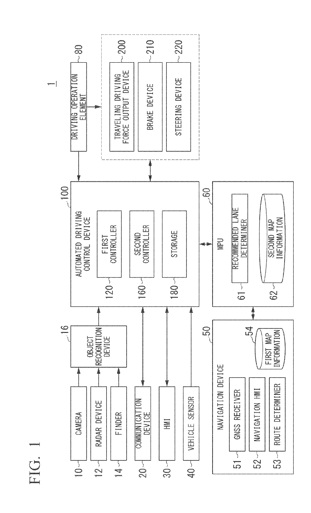
[0037][Overall constitution]FIG. 1 is a constitution diagram of a vehicle system 1 using the vehicle control device according to a first embodiment. A vehicle (hereinafter, referred to as a subject vehicle M) in which the vehicle system 1 is mounted is, for example, a vehicle such as a two-wheeled vehicle, a three-wheeled vehicle, or a four-wheeled vehicle, and a driving source of the vehicle includes an internal combustion engine such as a diesel engine or a gasoline engine, an electric motor, or a combination thereof. The electric motor operates using electric power generated by a generator connected to the internal combustion engine, or discharge power of a secondary battery or a fuel cell.
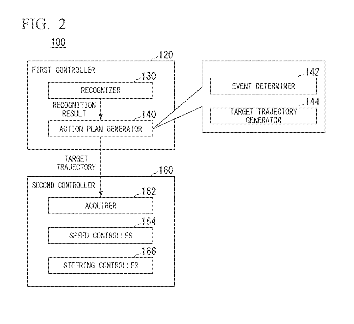
[0038]For example, the vehicle system 1 includes a camera 10, a radar device 12, a finder 14, an object recognition device 16, a communication device 20, a human machine interface (HMI) 30, a vehicle sensor 40, a navigation device 50, a map-positioning unit (MPU) 60, a driving operation element...
second embodiment
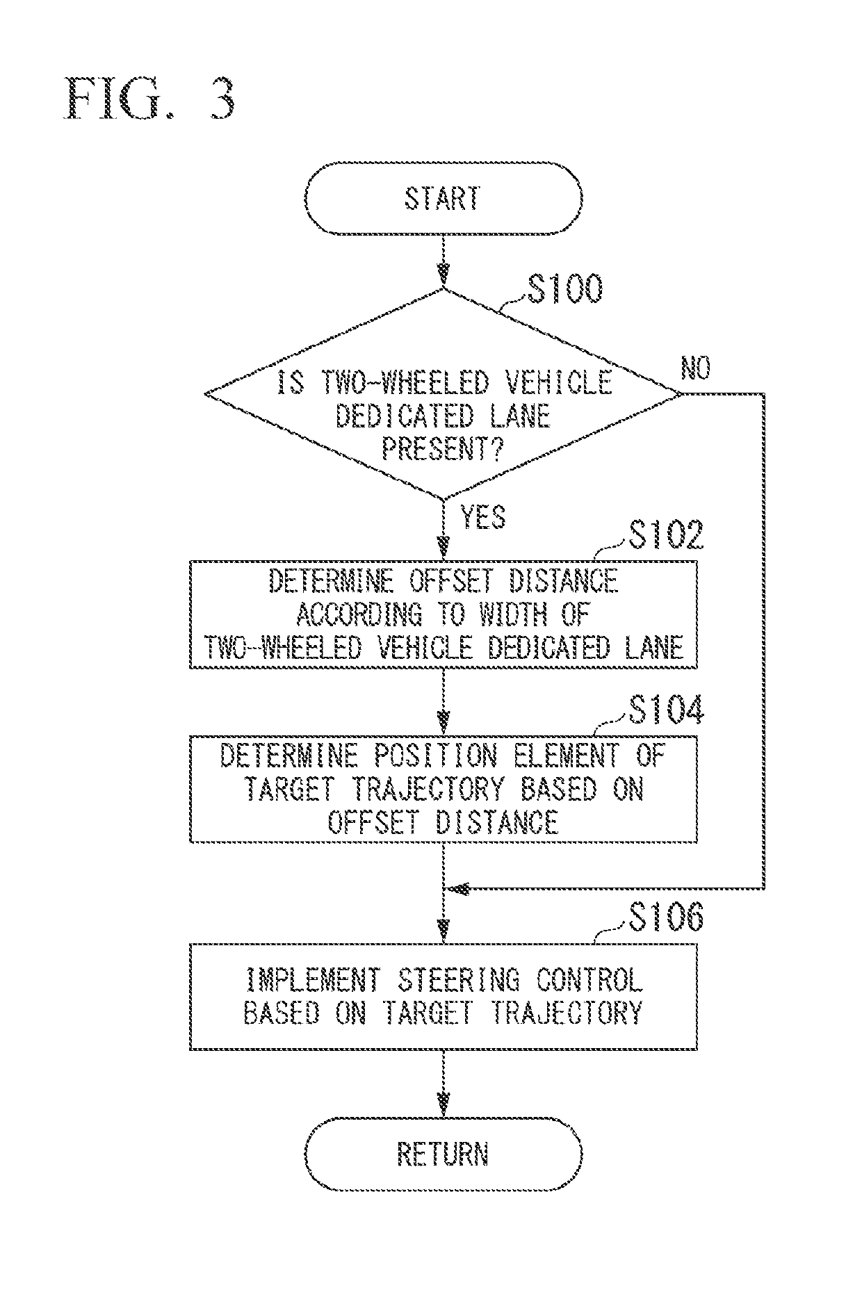
[0096]Hereinafter, a second embodiment will be described. The second embodiment is different from the above-described first embodiment in that, in a case where the adjacent lane that is adjacent to the subject lane is the two-wheeled vehicle dedicated lane, at a point where it is easy for the two-wheeled vehicle to enter the two-wheeled vehicle dedicated lane from the outside of the road, the subject vehicle M is caused to move far away from the two-wheeled vehicle dedicated lane in comparison with at other points. For example, the point where it is easy for the two-wheeled vehicle to enter the two-wheeled vehicle dedicated lane from the outside of the road is a point where the two-wheeled vehicle dedicated lane appears next to the subject lane (hereinafter, referred to as a start point). Hereinafter, differences from the first embodiment will be mainly described, and descriptions of functions and the like that are the same as in the first embodiment will be omitted.
[0097]For exampl...
third embodiment
[0103]Hereinafter, a third embodiment will be described. The third embodiment is different from the first and second embodiments described above in that in a case where a structure such as a fence or a pole (hereinafter, referred to as a lane separation structure ST2) is present at a boundary between the two-wheeled vehicle dedicated lane and the subject lane, and the two-wheeled vehicle dedicated lane and the subject lane are physically partitioned, the subject vehicle M is caused to be closer to the two-wheeled vehicle dedicated lane, in comparison with a case where the two-wheeled vehicle dedicated lane and the subject lane are not physically partitioned by the lane separation structure ST2. Hereinafter, differences from the first and second embodiments will be mainly described, and descriptions of functions and the like the same as in the first and second embodiments will be omitted.
[0104]The recognizer 130 in the third embodiment recognizes the lane separation structure ST2 tha...
PUM
 Abstract
Description
Claims
Application Information
 - R&D
- Intellectual Property
- Life Sciences
- Materials
- Tech Scout
- Unparalleled Data Quality
- Higher Quality Content
- 60% Fewer Hallucinations
Browse by: Latest US Patents, China's latest patents, Technical Efficacy Thesaurus, Application Domain, Technology Topic, Popular Technical Reports.
© 2025 PatSnap. All rights reserved.Legal|Privacy policy|Modern Slavery Act Transparency Statement|Sitemap|About US| Contact US: help@patsnap.com


