Series motor with permanent magnet

a series-wound motor and permanent magnet technology, applied in the direction of dynamo-electric machines, electrical apparatus, magnetic circuits, etc., can solve the problems of series-wound motors, (unregulated) no-load rotation speed is considerably higher than the (unregulated) rated rotation speed, and the use of series-wound motors is problematic, so as to reduce the no-load rotation speed, the effect of high no-load rotation speed and high rated rotation speed

Inactive Publication Date: 2012-05-17
C & E FEIN
View PDF3 Cites 2 Cited by
  • Summary
  • Abstract
  • Description
  • Claims
  • Application Information

AI Technical Summary

Benefits of technology

[0032]This is particularly advantageous for those applications in which the (unregulated) no-load rotation speed must be limited. This makes it possible to at least partially compensate for the design-dependent disadvantages of universal motors, which lead to a high no-load rotation speed in comparison to the rotation speed on load.
[0033]According to one development of this embodiment, a flat in the rotation-speed/torque characteristic, which is caused by the at least one permanent magnet, in comparison to the series-wound motor without a permanent magnet is used by adaptation of the windings to form a peak in the torque in the working range, while at the same time reducing the no-load rotation speed to a permissible value.
[0034]In comparison to the same motor without permanent magnets, the modified motor winding results in a higher rated rotation speed with the same torque. This allows a higher gearbox step-down rati...

Problems solved by technology

However, series-wound motors have the disadvantage that the (unregulated) no-load rotation speed is considerably higher than the (unregulated) rated rotation speed when operated on ...

Method used


Image

  • Series motor with permanent magnet
  • Series motor with permanent magnet
  • Series motor with permanent magnet

Examples


Embodiment Construction

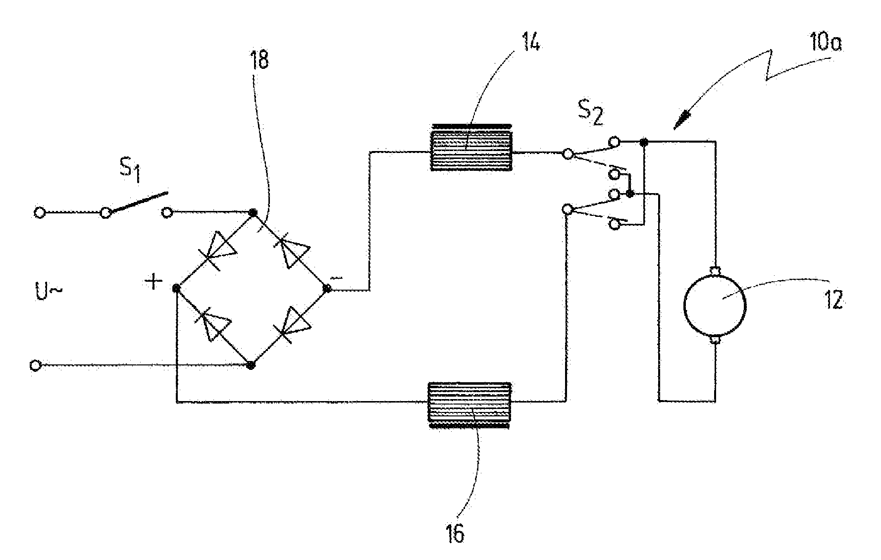
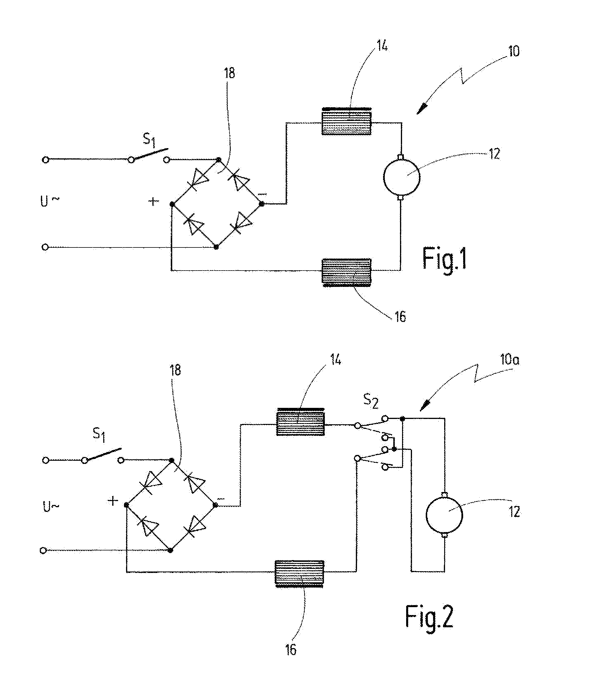
[0046]FIG. 1 shows a circuit of a series-wound motor according to the invention, which is annotated 10 overall.

[0047]The series-wound motor 10 has an armature 12 with an armature winding which is connected in series with two field windings 14, 16. The motor is supplied with alternating current from an AC voltage source U˜ (for example 230 V, 50 Hz). A motor switch S1 is used for switching on and off. The AC voltage is rectified via a rectifier 18 in the form of a bridge rectifier, thus resulting in this being supplied as a pulsating DC voltage. Furthermore, the bridge rectifier may have means for smoothing (for example a capacitor, not illustrated). In addition to the two field windings 14, 16 which produce the main excitation, the series-wound motor 10 has permanent magnets, which are each introduced into a flat slot in a pole shoe.

[0048]Various possible arrangements of the permanent magnets on the stator 26 will be explained briefly in the following text with reference to FIGS. 4 ...


PUM


Abstract

A series-wound DC motor is disclosed comprising a stator having at least two poles and an armature, each pole comprising at least one field winding which is connected in series with an armature winding, and further comprising at least one permanent magnet arranged on each pole, whose magnetic field is superimposed on the main field produced by the at least one field winding.

Description

CROSSREFERENCES TO RELATED APPLICATIONS[0001]This application is a continuation of International Patent Application PCT / EP2010 / 060742, filed on Jul. 23, 2010 designating the U.S., which International Patent Application was published in German language and claims priority from German patent application 10 2009 037 114.1, filed on Jul. 31, 2009. The entire contents of these priority applications are incorporated herein by reference.BACKGROUND OF THE INVENTION[0002]The invention relates to a series-wound motor having a stator and an armature, having at least one field winding which is connected in series with an armature winding, and having at least one permanent magnet, whose magnetic field is superimposed on the main field produced by the at least one field winding.[0003]In principle, it is known in the prior art (cf. DD 109 775, DD 145 590, DE-PS1 181 309, EP 0 582 416 B1) to provide an auxiliary series winding for direct-current motors with permanent-magnet excitation, in order to ...

Claims


Application Information

Patent Timeline
IPC IPC(8): H02K21/04H02K23/66H02K7/14H02K11/04
CPCH02K23/08H02K23/04
Inventor DIETL, LOTHAR
Owner C & E FEIN
Why Eureka
Try Eureka