
Eureka
For R&D, Eureka makes reading and utilizing patents & technical documents easy.
Eureka AIR
Designed for self-driven R&D workflows. Generate viable solutions, solve complex R&D challenges, empower your innovation with AI.

Eureka Materials
Designed for material experts only. Revolutionize your material R&D, from search, analyze, to developing new materials.

TechResearch
Generate reliable direction feasibility study reports for your R&D in just a few steps.

TechSeek
Discover and master advanced knowledge NOW. Basics, ideas, possibilities, all at once.

TechMind
As an expert in R&D Theories, TechMind can generates customized viable solutions instantly.

TechRisk
Analyze your overall solution with one click, know your potential R&D risks in advance.

TechMonitor
Get weekly tech updates, stay abreast of the latest tech innovations and key insights.
Brake Device for a Trolley
- Summary
- Abstract
- Description
- Claims
- Application Information
AI Technical Summary
Benefits of technology
Problems solved by technology
Method used
Image

Examples
Embodiment Construction
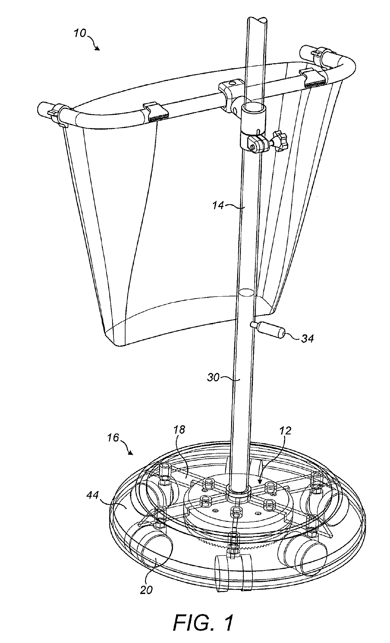
[0019]FIG. 1 illustrates a typical trolley 10 for medical equipment in which a brake device 12 in accordance with the present invention is incorporated. The trolley 10 in this example has a central upright pole 14, to which medical equipment may be attached, and a base 16 comprising a number of radiating feet 18 each attached to a swivel castor wheel assembly 20. The base 16 is covered by a protective skirt 44 which is described further below. In this figure, the skirt 44 is shown transparent in order to illustrate the components below.
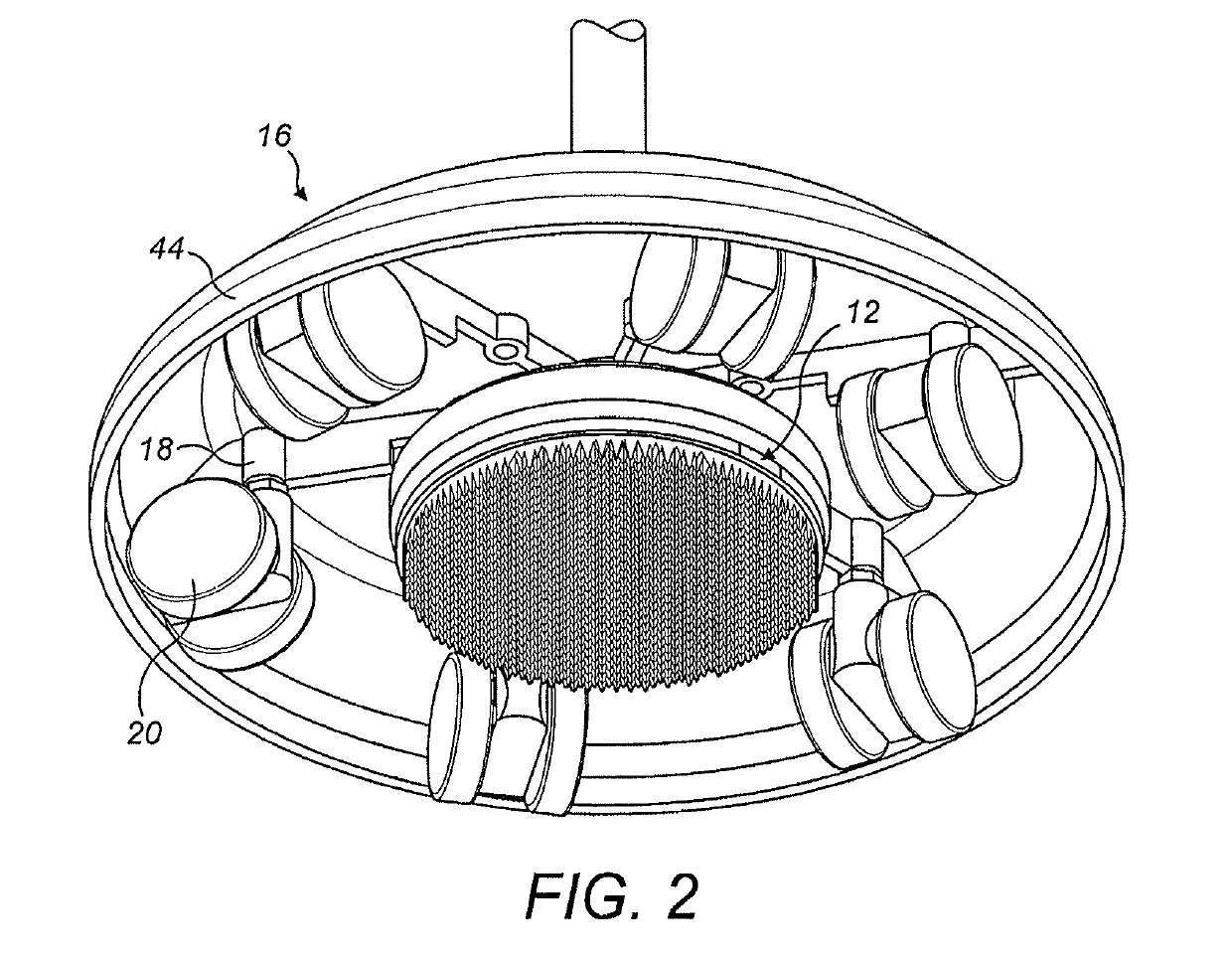
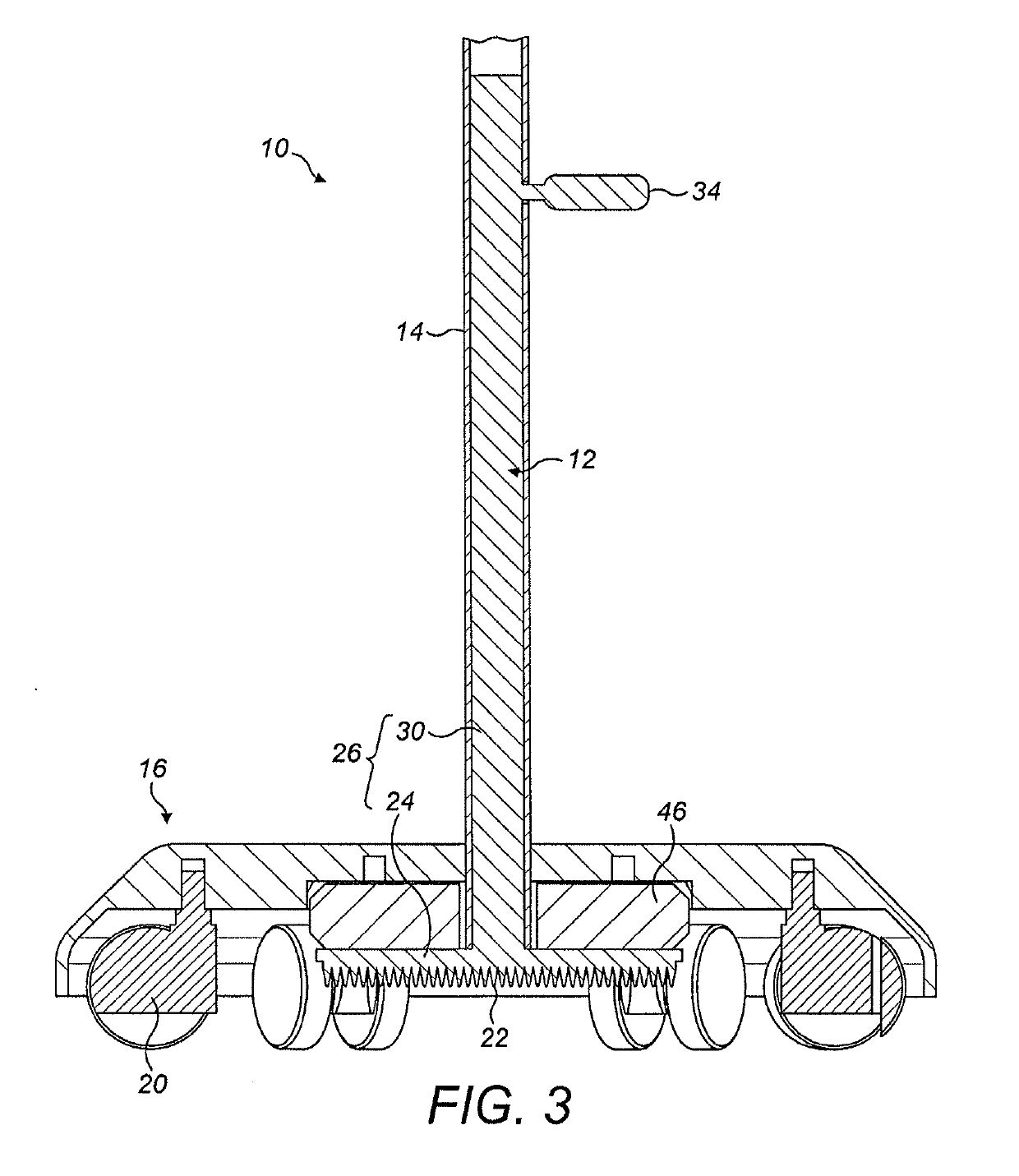
[0020]The brake device 12 comprises a deformable brake pad 22 secured to a release mechanism 26. The brake pad 22 is located substantially centrally beneath the trolley base 16, radially inwardly of the wheels 20 as seen in FIG. 2. In the raised or retracted position, the brake pad 22 is held just beneath the radiating feet 18 and spaced above the floor surface on which the wheels 20 rest, as in FIG. 3. In this position, the trolley 10 can move freely...
PUM
 Abstract
Description
Claims
Application Information
 - R&D Engineer
- R&D Manager
- IP Professional
- Industry Leading Data Capabilities
- Powerful AI technology
- Patent DNA Extraction
Browse by: Latest US Patents, China's latest patents, Technical Efficacy Thesaurus, Application Domain, Technology Topic, Popular Technical Reports.
© 2024 PatSnap. All rights reserved.Legal|Privacy policy|Modern Slavery Act Transparency Statement|Sitemap|About US| Contact US: help@patsnap.com