
Modulated electromagnetic musical system and associated methods

a musical system and electromagnetic technology, applied in the field of modulated electromagnetic musical system, can solve the problems of lack of technology that allows the flexibility of modulation found on sound synthesizers, limitations of acoustic tremolo effects, and limited frequency range of modulators

Active Publication Date: 2019-10-03
TRUSTEES OF DARTMOUTH COLLEGE THE
View PDF14 Cites 3 Cited by
  • Summary
  • Abstract
  • Description
  • Claims
  • Application Information

AI Technical Summary

Benefits of technology

This patent explains how two signals can create intermodulation products, which can produce rich frequency content. This content can be used to create sound. The patent also mentions the use of harmonic oscillators, which are another way to produce frequency modulation. Overall, the patent explains how certain technical methods can be used to create musical sounds and sounds that maneuver through frequency modulation.

Problems solved by technology

The acoustic tremolo effect has some limitations, in that; the frequency range of the modulator is limited to low frequency oscillation below 100 Hz.
There currently lacks technology that allows the flexibility of modulation found on sound synthesizers on acoustic or augmented acoustic instruments.

Method used


Image

  • Modulated electromagnetic musical system and associated methods
  • Modulated electromagnetic musical system and associated methods
  • Modulated electromagnetic musical system and associated methods

Examples


second embodiment

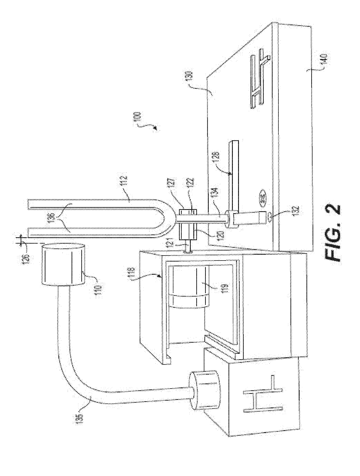
[0057]A second embodiment is shown in FIG. 2, therein illustrated an electromagnetically augmented musical instrument system 100 in accordance with the present invention. The system 100 includes an actuator 110, an acoustic carrier harmonic oscillator 112, a dampening system 118, dampener material 120, a limited cross section of the acoustic carrier harmonic oscillator 122, a distance (not shown) between the dampener 18 and the acoustic carrier harmonic oscillator 112, a distance 126 between the actuator 10 and the acoustic carrier harmonic oscillator, an amplifier interface 128, a soundboard or amplifier resonator 130, isolation pads 132, and a structural frame 135. It is foreseen that the electromagnetically augmented musical instrument system 100 may further include amplification circuitry (not shown), as well as a transducer (not shown), such as a microphone or speaker.

[0058]In the illustrated example of FIG. 2, the actuator 110 is substantially similar to the actuator 10. The a...

third embodiment

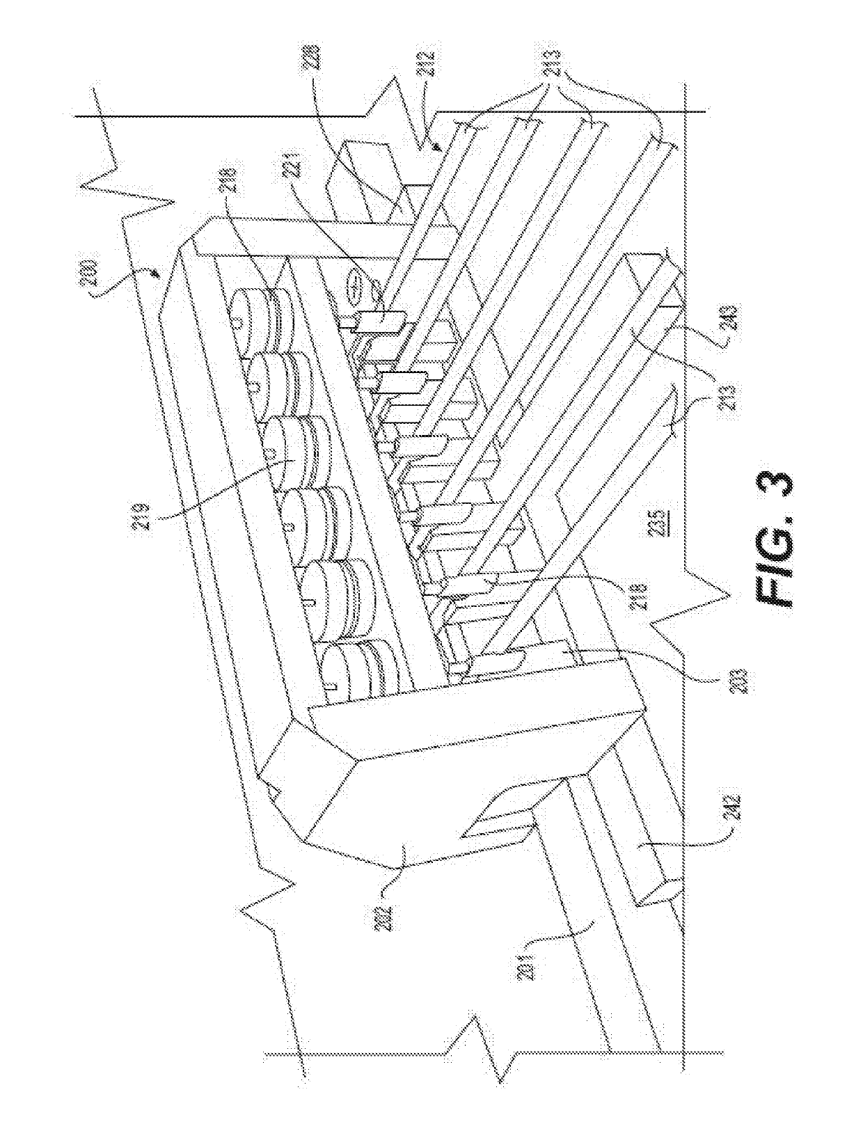
[0067]the present invention is shown in FIG. 3, therein illustrated an electromagnetically augmented musical instrument system 200 in accordance with the present invention. The system 200 includes an instrument bridge 201, a series of acoustic carrier harmonic oscillators 212, a dampening subassembly 218, a spring suspension system 228, and an instrument body 235. It is foreseen that the electromagnetically augmented musical instrument system 200 may further include amplification circuitry (not shown), as well as a transducer (not shown), such as a microphone, sensor, or speaker.

[0068]In the illustrated example of FIG. 3, the series of acoustic carrier harmonic oscillators 212 are illustrated as six individual strings 213 terminated at the bridge 201, each string 213 is actuated at its natural frequency by a user to generate force by bowing, plucking, striking, rubbing, or blowing and is not electromagnetically activated. It is foreseen that the musical instrument system could inclu...


PUM


Abstract

A modulated electromagnetic musical instrument and sound reproduction system includes an acoustic carrier signal source, a modulation signal source, a linkage element, and an acoustic output. The acoustic carrier signal source is produced electromagnetically or mechanically via human instrument playing. An electromagnetic modulation source mixes with the acoustic carrier signal within a linkage element to produce a nonlinear behavior. This nonlinear behavior's coupled interaction with a physical medium or acoustic body produces sideband frequency components to form unique musical sound outputs and audio effects.

Description

RELATED APPLICATIONS[0001]This application claims priority to U.S. Patent Application Ser. No. 62 / 360,445, titled “Electromagnetically Augmented Musical Instrument Methods and Systems,” filed Jul. 10, 2016, and incorporated herein by reference in its entirety.BACKGROUND OF THE INVENTION[0002]Musical instruments, such as the strings, horns, brass, woodwinds, and percussion of the modern orchestra and the multitude of other non-western instruments from around the world have been known for centuries. Conventional musical instrument development has attempted to create new behaviors and new sounds, from both a purely acoustic and electroacoustic perspective. For example, modern guitars have developed significantly since the early invention of the first guitar. Similarly, the invention of the synthesized drum or drum machine provided an entirely new palette of sonic options.[0003]In an electroacoustic musical instrument, a substantially acoustic signal is converted to an electric represen...

Claims


Application Information

Patent Timeline
Patent Type & Authority Applications(United States)
IPC IPC(8): G10H3/22G10H3/26
CPCG10H3/22G10H2220/461G10H3/26G10H1/0058G10H3/143G10H3/146G10H3/18G10H3/20G10H5/02G10D99/00G10F1/18G10G1/04
Inventor TOPEL, SPENCERCHANG, HERBERT H.C.
Owner TRUSTEES OF DARTMOUTH COLLEGE THE
Learn More